Master cylinder

a master cylinder and cylinder head technology, applied in the field of master cylinders, can solve the problems of high flow, insufficient inability to achieve sufficient flow rate of brake fluid, so as to shorten the ineffective stroke, promote the effect of fast fill function and no fluid flow resistan

Inactive Publication Date: 2008-11-18
HITACHI LTD
View PDF11 Cites 2 Cited by
  • Summary
  • Abstract
  • Description
  • Claims
  • Application Information

AI Technical Summary

Benefits of technology

[0025]Further, according to another aspect of the invention, there is provided a master cylinder comprising a stepped cylinder having a large diameter cylinder portion and a small diameter cylinder portion; a stepped piston having a large diameter piston portion slidably inserted into the large diameter cylinder portion of the stepped cylinder and a small diameter piston portion slidably inserted into the small cylinder portion of the stepped cylinder; a reverse flow checking opening and closing portion for partitioning the inside of the stepped cylinder into a large diameter pressurizing chamber on the large diameter piston portion side and a small diameter hydraulic chamber on the small diameter piston portion side and permitting a brake fluid to flow only from the large diameter pressurizing chamber side to the small diameter hydraulic chamber; a cut-off portion on the large diameter pressurizing chamber side for cutting communication between the large diameter pressurizing chamber and a reservoir by being closed by sliding movement of the stepped piston to the small diameter hydraulic chamber; and a cut-off portion on the small diameter hydraulic chamber side for cutting communication between the large diameter pressurizing chamber and the small diameter hydraulic chamber by being closed by the sliding movement of the stepped piston to the small diameter hydraulic chamber side, the brake fluid being supplied from the large diameter pressurizing chamber side to the small diameter hydraulic chamber side by the opening operation of the reverse flow checking opening and closing portion by reducing a volume of the large diameter pressurizing chamber by the sliding movement of the stepped piston to the small diameter hydraulic chamber side, wherein an ineffective stroke of the stepped piston until the cut-off portion on the small diameter hydraulic chamber side is brought into the closed state is made longer than an ineffective stroke of the stepped piston until the cut-off portion on the large diameter pressurizing chamber side is brought into a closed state.
[0026]When constituted in this way, in supplying the brake fluid from the large diameter pressurizing chamber to the small diameter hydraulic chamber, even when the cut-off portion on the small diameter hydraulic chamber side having the long

Problems solved by technology

Meanwhile, there poses a problem that since the above-described master cylinder is provided with the notch, when the pressure is elevated slowly, the fluid of the large diameter pressurizing chamber flows to the reservoir and the fast fill cannot be carried out sufficiently.
However, when the ineffective stroke is simply set to be short, sectional areas of flow paths of the cut-off portion on the side of the small diameter hydraulic chamber and the cut-off portion on the side of the large diameter pressurizing chamber, are narrowed.
When the sectional areas of the flow paths are narrowed in this way, in the case that the master cylinder is used in a combination with a traction control ap

Method used


Image

  • Master cylinder
  • Master cylinder
  • Master cylinder

Examples


first embodiment

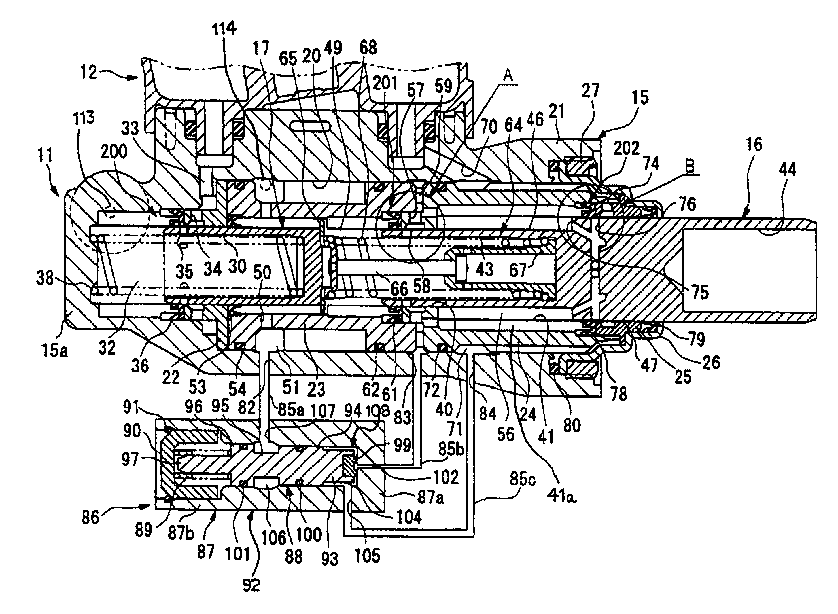
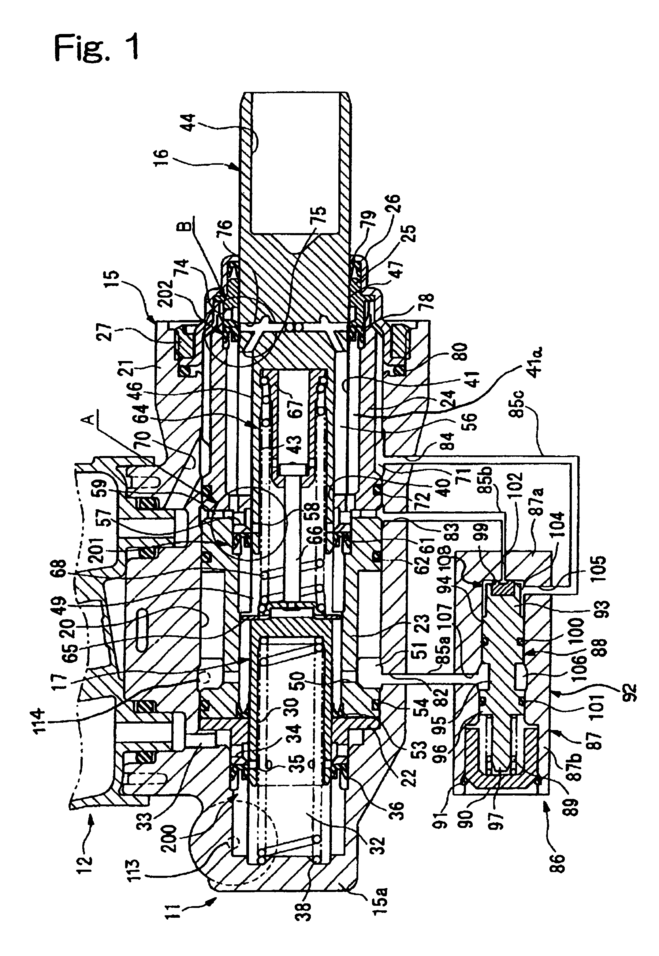
[0042]An explanation will be given of a master cylinder according to the invention in reference to FIG. 1 through FIG. 10.

[0043]FIG. 1 shows the master cylinder of the first embodiment and here, notation 11 designates a master cylinder main body for generating a brake hydraulic pressure in accordance with an input of a brake pedal introduced via a booster (not shown), and notation 12 designates a reservoir attached to an upper portion of the master cylinder main body 11 for storing a brake fluid which is charged to and discharged from the master cylinder main body 11.

[0044]The master cylinder main body 11 is provided with a stepped cylinder 15 having a shape of a substantially bottomed cylinder along a horizontal direction, a primary piston (stepped piston) 16 slidably fitted to portion (right side in FIG. 1) of the stepped cylinder 15, and a secondary piston 17 slidably fitted to the stepped cylinder 15 closer to a bottom portion 15a side (left side in FIG. 1), which is described l...

second embodiment

[0121]Further, the lid member 90 of the control valve 86 is screwed to the valve cylinder main body 87 and an O-ring (ring seal) 111 is provided therebetween for sealing a clearance therebetween. Thereby, an interval between the valve cylinder 92 and a side of the valve piston 88 opposed to the fluid chamber 104, constitutes a damper chamber 112 arranged with the valve spring 89 and operated with the hydraulic pressure. The damper chamber 112 communicates with the fluid chamber 104 via the throttle path 110 (in other words, the other end side of the throttle path 110 opposed to the fluid chamber 104, is opened to the damper chamber 112).

[0122]Next, an explanation will be given of operation of the master cylinder according to above-described second embodiment.

[0123]When the primary piston 16 is pressed toward the bottom portion 15a by the rod of the booster connected to the brake pedal, the large diameter pressurizing chamber 56 and the primary side small diameter hydraulic chamber ...


PUM


Abstract

A master cylinder of the invention supplies a brake fluid from a large diameter pressurizing chamber 56 to a small diameter hydraulic chamber 49 by opening a reverse flow checking opening and closing portion 61 by sliding movement of a stepped piston 16 forwardly, that is, fast fill and when the hydraulic pressure of the large diameter pressurizing chamber 56 rises, a control valve 86 escapes the hydraulic pressure of the large diameter pressurizing chamber 56 to a reservoir 12 to gradually lower in accordance with rise of the hydraulic pressure of the small diameter hydraulic chamber 49, thereby capable of reducing a strange feeling in a pedal feeling caused by sudden pressure release of the large diameter pressurizing chamber 56.

Description

BACKGROUND OF THE INVENTION[0001]1. Field of the Invention[0002]The present invention relates to a master cylinder for supplying a brake fluid to a brake apparatus of an automobile or the like.[0003]2. Description of the Related Art[0004]As a conventional master cylinder, as described in a microfilm of A Japanese Utility Model Application No. 152602 / 1980 (Japanese Utility Model Laid-Open No. 73248 / 1982), there is provided a constitution in which by carrying out so-to-speak fast fill for supplying a large volume of a brake fluid at an initial stage of operation when the brake fluid is supplied to a brake apparatus such as a disk brake or a drum brake, an ineffective fluid amount at an initial stage of stroke is compensated for, and as a result, a pedal stroke can be shortened (fast fill type master cylinder).[0005]The fast fill type master cylinder is provided with a stepped cylinder having a large diameter cylinder portion and a small diameter cylinder portion, a stepped piston havi...

Claims


Application Information

Patent Timeline
IPC IPC(8): B60T11/224B60T11/16B60T11/26
CPCB60T11/224B60T11/26B60T11/16
Inventor OGIWARA, TAKATOSANO, KENJIKOSHIMIZU, NAGANORIANDO, HIROMI
Owner HITACHI LTD
Why Eureka
Try Eureka