Method and system for displaying an analog image by a digital display device

a digital display device and analog image technology, applied in the field of graphics systems, can solve the problems of jitter in both reference signals, the reference frequency can drift over a prolonged period of time, and the integration difficulty of a relatively small-sized integrated circuit, so as to achieve considerable flexibility and instantaneous change of the bandwidth of the pll

Inactive Publication Date: 2009-07-21
GENESIS MICROCHIP DELAWARE
View PDF114 Cites 1 Cited by
  • Summary
  • Abstract
  • Description
  • Claims
  • Application Information

AI Technical Summary

Benefits of technology

[0030]The clock recovery circuit includes a digital phase-locked loop (PLL). The bandwidth of the PLL can be instantaneously changed because of the digital implementation. In addition, the long term frequency and the temporary phase fluctuations are tracked using different control loops. As a result, considerable flexibility is available to a designer to track the time reference signal.

Problems solved by technology

In addition, the reference frequency can drift over a prolonged period of time due to, for example, temperature changes in the circuits generating the analog source image data.
Further, jitter may be present in both the reference signal and the clock signal generated by the analog PLL.
However, such a low bandwidth generally requires a capacitor having a large size, which may be hard to integrate into a relatively small-sized integrated circuits.
One problem with this approach is that noise is introduced into the analog PLL loop due to the external couplings.
Analog PLLs are generally sensitive to such noises, leading to instability in the PLL loop.
Without a low bandwidth in the loop, PLL 200 may be unable to track deviations in the reference signal closely, which may be unacceptable in some situations as explained below.
These deviations are usually more problematic for larger size display screens.
Such a skew between lines is generally perceptible for the human eye and the resulting display quality may be unacceptable.

Method used


Image

  • Method and system for displaying an analog image by a digital display device
  • Method and system for displaying an analog image by a digital display device
  • Method and system for displaying an analog image by a digital display device

Examples


Embodiment Construction

[0042]1. Overview and Discussion of the Invention

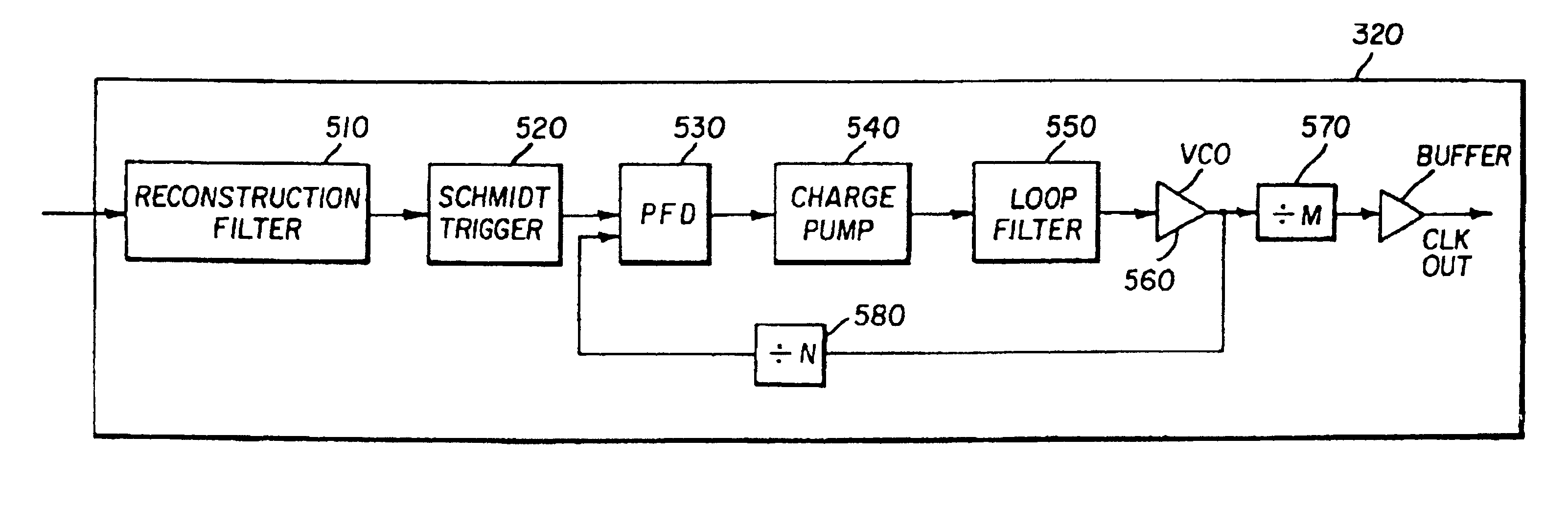
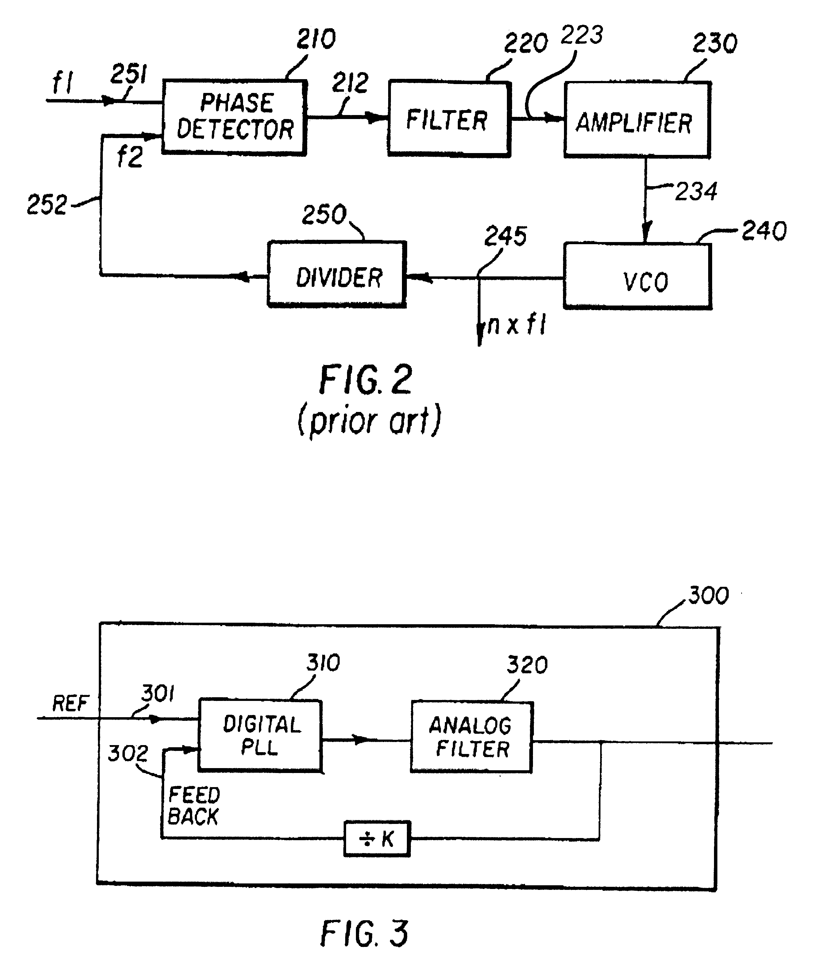
[0043]The present invention is described in the context of clock recovery circuit 300 (FIG. 3) which includes digital PLL circuit 310 and analog filter 320. The output of PLL circuit 310 is coupled to the input of analog filter 320. PLL circuit 310 is implemented using digital components and signals.

[0044]In operation, PLL circuit 310 receives as input a time reference 301 and generates output signal 312. While generating the output signal, PLL signal 310 attempts to synchronize the output signal 312 with time reference. Analog filter 320 filters any undesirable spectral components in the output signal 312 and provides the filtered signal as input to PLL circuit on input 302.

[0045]PLL circuit 310 is implemented using digital components and a designer is provided considerable flexibility to specify the degree or manner in which output signal 312 should track reference signal 301. Due to such a flexibility, the bandwidth of PLL circuit ...


PUM


Abstract

A clock recovery circuit in a digital display unit for recovering a time reference signal associated with analog display data. The clock recovery circuit includes a phase-locked loop (PLL) implemented in digital domain and an analog filter to eliminate any undesirable frequencies from the output signal of the PLL. The PLL includes independent control loops to track long term frequency drifts of the time reference signal and the transient phase differences respectively. By providing such independent control loops, the generated clock can be better synchronized with the time reference signal.A system and method for displaying an analog source image by a digital display unit. A converter circuit generates a plurality of digital source image elements from an analog source image based upon a sampling clock signal synchronized with a time reference signal associated with the analog source image. A scaler unit receives the digital source image elements in accordance with a first clock signal, scales the source image elements independently in both vertical and horizontal directions to form destination image elements, and provides the destination image elements to the display unit in accordance with a second clock signal. The first clock signal and the second clock signal are arranged such that a source frame rate and a destination frame rate are substantially equal.

Description

CROSS REFERENCE TO RELATED APPLICATIONS[0001]More than one reissue application has been filed for the reissue of U.S. Pat. No. 6,320,574. The reissue applications are application Ser. No. 10 / 720,001(the present application), (Ser. No. 11 / 408,528) and (Ser. No. 11 / 408,669) all of which are divisional reissues of U.S. Pat. No. 6,320,574.<?insert-end id="INS-S-00002" ?>RELATED APPLICATIONS[0002]The present application is related to co-pending U.S. Patent Application entitled, “A Method and Apparatus for Upscaling an Image”, Filed Concurrently with the present application, Serial Number UNASSIGNED, Attorney Docket Number: PRDN-0001, and is incorporated in its entirety herewith.[0003]The present application is also related to and is a continuation of application Ser. No. 08 / 803,824 filed Feb. 24, 1997, now U.S. Pat. No. 5,796,392, entitled, “Method and Apparatus for Clock Recovery in a Digital Display Unit.”BACKGROUND OF THE INVENTION[0004]1. Field of the Invention[0005]The present...

Claims


Application Information

Patent Timeline
Patent Type & Authority Patents(United States)
IPC IPC(8): G09G5/00G06F15/00H03L7/00H04N9/475G09G3/20H03L7/06H03L7/07H03L7/085H03L7/093
CPCG09G5/008H03L7/07H03L7/085H03L7/093G06F1/04G09G3/20
Inventor EGLIT, ALEXANDER J.
Owner GENESIS MICROCHIP DELAWARE
Why Eureka
Try Eureka