Lubricating device for a plurality of lubricating stations

a lubricating device and a technology for lubricating stations, applied in knitting, hoisting equipment, gearing, etc., can solve the problems of increasing water, affecting the lubricating process, and inconvenient supply of oil to the lubricating station, so as to prolong the lubricating process and keep the resilience (elasticity) of the lines under initial stress.

Inactive Publication Date: 2009-09-01
MEMMINGER IRO GMBH
View PDF18 Cites 1 Cited by
  • Summary
  • Abstract
  • Description
  • Claims
  • Application Information

AI Technical Summary

Benefits of technology

[0015]For monitoring proper operation of the lubricating device, a sensor device that detects and monitors the reciprocating motion of the piston can be advantageous. It may suffice to monitor whether the piston attains a certain stroke or not. For instance, if one lubricating conduit is stopped up, the piston is unable to pump any lubricant into this conduit and is accordingly blocked. It fails to reach the switching point of the sensor device, and the sensor device detects this and turns off the affected machine.
[0016]Another aspect of the invention is directed to a method for the lubrication of lubricating stations of a machine by means of at least one pump via lines. Lubricant is pumped discontinuously by the pump to the lubricating stations via the lines. For lubricant supply to one or more lubricating stations, the applicable line or lines are subjected by the pump to a pressure that fluctuates over time. Regardless of the specific design of the pump device and distributor devices in attached lines, and regardless of how many lubricating stations are connected, it is expedient for the pump pressure to be modulated during individual lubricating pulses. If a stepping motor is used to drive the pump, its individual steps can be converted into micropumping pulses, whose train forms a lubricating pulse. The intervals between individual micropumping pulses are expediently dimensioned such that the pressure in the lines does not drop below a minimum limit value. The minimum pressure is preferably somewhat less than the requisite injection pressure for the connected nozzles. It suffices to keep any resilience (elasticity) of the lines under initial stress. This makes it possible either to meter especially small quantities of lubricant, or to prolong the lubricating process.

Problems solved by technology

As a rule, failure of the lubrication leads to increased water and early failure of the knitting machine.
It is counterproductive to supply too much oil to the lubricating stations.
For instance, if one lubricating conduit is stopped up, the piston is unable to pump any lubricant into this conduit and is accordingly blocked.
It fails to reach the switching point of the sensor device, and the sensor device detects this and turns off the affected machine.

Method used


Image

  • Lubricating device for a plurality of lubricating stations
  • Lubricating device for a plurality of lubricating stations
  • Lubricating device for a plurality of lubricating stations

Examples


Embodiment Construction

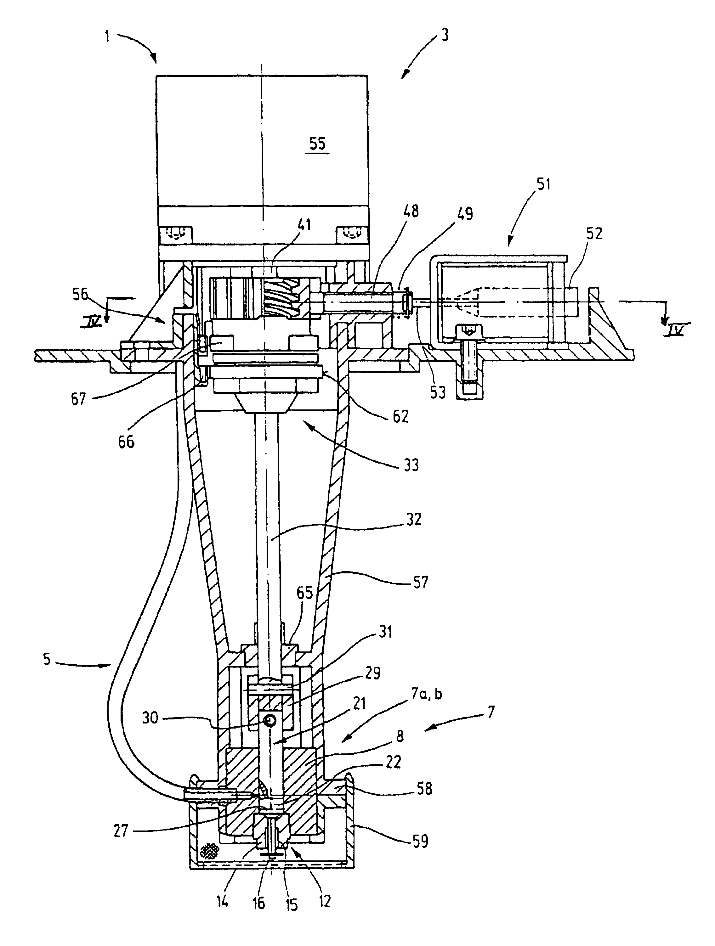
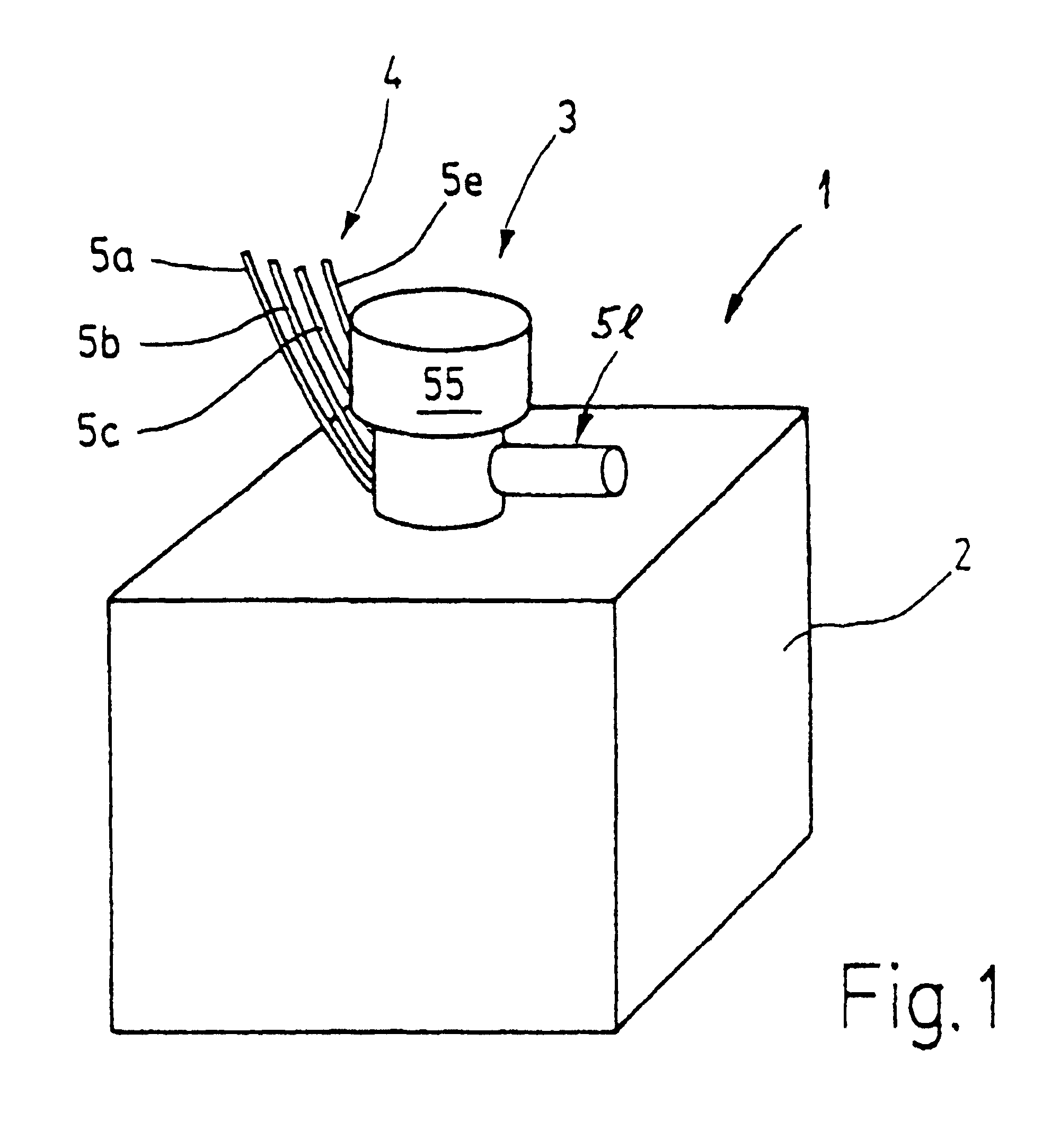
[0027]In FIG. 1, a lubricating device 1 is shown, which includes a supply container 2, for lubricant, such as oil. A distributor and pump unit 3 is inserted into the supply container 2 and dispenses predetermined portions of lubricant at predetermined times to a group 4 of lubricant lines 5a through 5e that lead away from it.

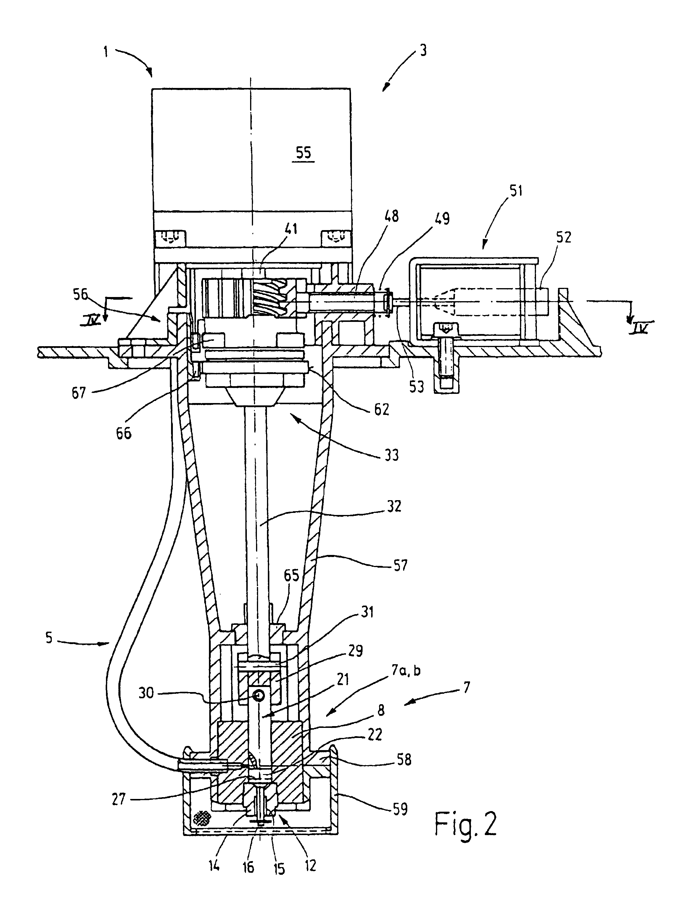
[0028]The pump and distributor unit 3 schematically shown in FIG. 1 is shown separately in FIG. 2. A piston pump 7, which is both a pump device 7a and a distributor device 7b simultaneously is used for pumping and allocating the lubricant. The piston pump 7, as seen particularly from FIGS. 3 and 7, includes a cylinder body 8 with a cylindrical through bore 9. The through bore 9 is embodied on its lower end in terms of FIGS. 2 and 7 as a stepped bore, because it has one portion 10 of increased diameter. This portion serves to receive a check valve 12, whose valve body 14 is screwed for instance into a corresponding thread in the portion 10.

[0029]The valve body 14...


PUM


Abstract

In a lubricating device for a plurality of lubricating stations, in particular for supplying lubricant to knitting machines, a pump device is provided that serves at the same time as a distributor device. To that end, the pump device has a piston which is provided with a control groove. The corresponding pump cylinder has an inlet and a plurality of outlets distributed over the cylinder wall. Depending on which of the outlets the control groove of the piston is made to coincide with, a corresponding lubricating station is selected. The pump device is thus a distributor device as well.

Description

FIELD OF THE INVENTION[0001]The invention relates to a lubricating device for a plurality of lubricating stations, especially for supplying lubricant, preferably oil, to lubricating stations of a knitting machine.BACKGROUND OF THE INVENTION[0002]In knitting machines, for instance, the needle drive requires constant lubrication, which is equally true for the needle guide in the needle bed or needle cylinder, and so forth. Yet satisfactory, regular lubrication is extremely important, precisely in modern high-speed knitting machines. The lubricating stations must be reliably supplied with oil. As a rule, failure of the lubrication leads to increased water and early failure of the knitting machine. On the other hand, the lubrication must be done in a thrifty way. It is counterproductive to supply too much oil to the lubricating stations. Such knitting machines are therefore often equipped with so-called pressure oilers or pressure oil lubricating systems, which feed oil under pressure f...

Claims


Application Information

Patent Timeline
Patent Type & Authority Patents(United States)
IPC IPC(8): F04B39/00F04B23/00F04B39/10F04B7/04F16H27/02F16H55/18D04B35/28F16N13/22F16N13/00F16N13/14
CPCD04B35/28Y10T74/1527Y10T74/19623F16N13/00
Inventor HUSS, ROLF
Owner MEMMINGER IRO GMBH
Why Eureka
Try Eureka