
Multi-phase locked loop for data recovery

a phase lock and data technology, applied in the field of phase lock loop for data recovery, can solve the problems of difficult to reduce clock jitter, worse clock jitter, etc., and achieve the effect of enhancing the tolerance for data random jitter and reducing clock jitter

Inactive Publication Date: 2009-10-20
REALTEK SEMICON CORP
View PDF6 Cites 4 Cited by
  • Summary
  • Abstract
  • Description
  • Claims
  • Application Information

AI Technical Summary

Benefits of technology

[0007]It is therefore an object of the present invention to provide a multi-phase-locked loop without dead zone, which can reduce clock jitter and provide higher tolerance for data random jitter.
[0008]Another object of the present invention is to provide a multi-phase-locked loop without static phase error.
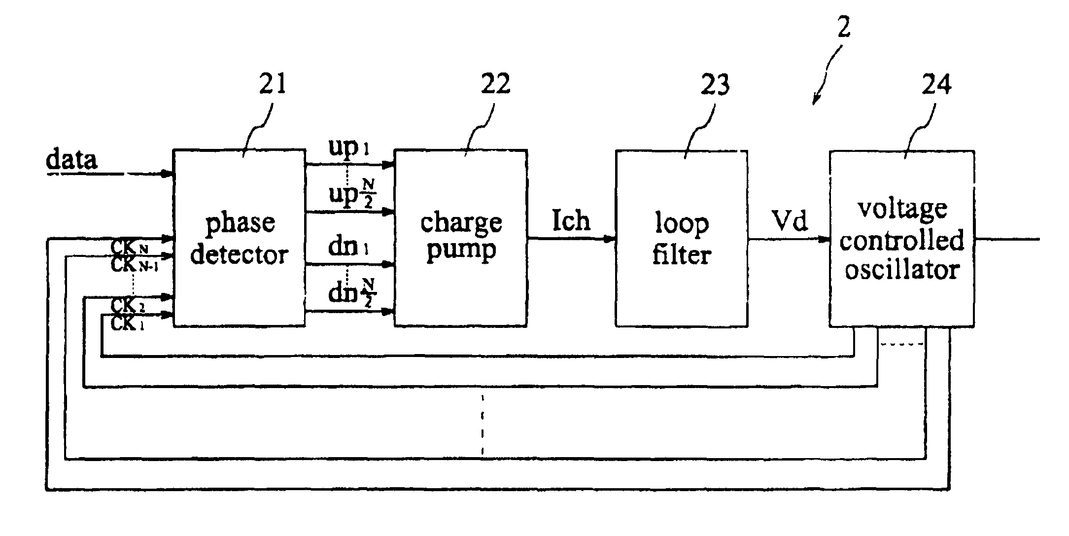
[0009]The present invention is characterized by a multi-phase-locked loop which can generate a plurality of multi-phase clock signals by a multi-phase voltage controlled oscillater to detect the transition edge of the data signal data. Accordingly, multiple sets of control signals (upk / dnk) are generated. Therefore, phase error θe and voltage Vd of the multi-phase-locked loop can be adjusted to be nearly linear according to the output control signals. This prevents the multiphase-locked loop from having dead zone. Furthermore, the clock jitter can be reduced and provide greater tolerance for data random jitter.
[0016]The multi-phase clock signal (CKj+1) which is applied to the (j+1)th phase detection unit (Uj+1) and the multi-phase clock signal (CKj) which is applied to the jth phase detection unit (Uj). In accordance with the invention, the relation between the phase error θe and the voltage Vd of the phase-locked loop can be adjusted to be nearly linear by employing these control signals. Therefore, a phase-locked loop without dead zone can be derived, which can reduce clock jitter and enhance the tolerance for data random jitter.

Problems solved by technology

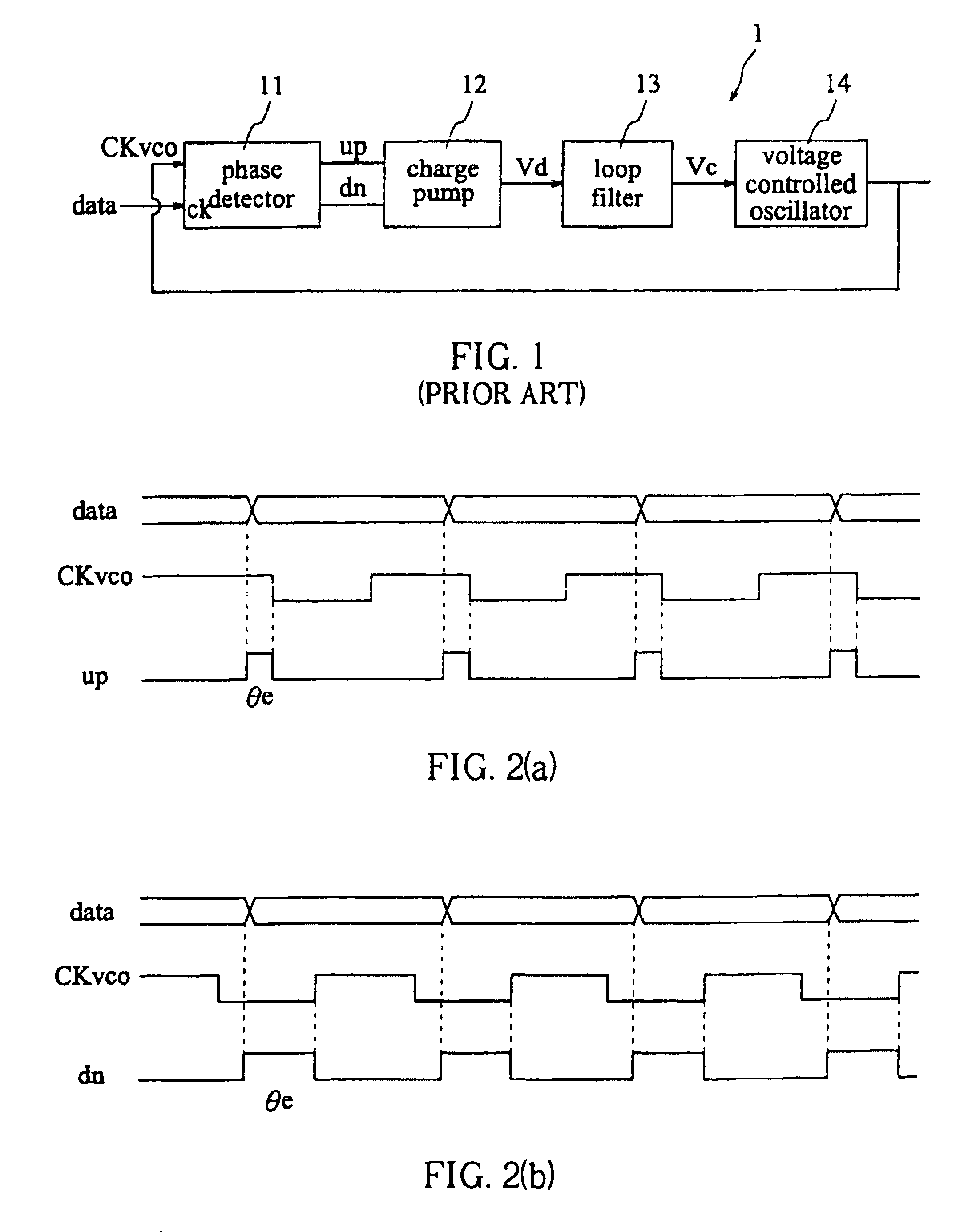
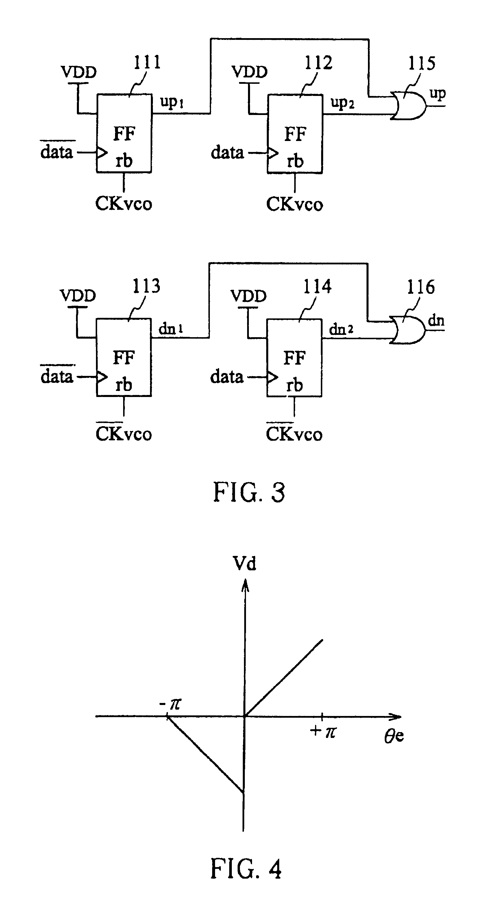
However, due to the above phenomenon, when the data signal data of the phase-locked loop has a phase lagging behind the clock signal CKvco, an obvious variation of Vd will be generated, which leads to clock jitter.
And, the tolerance for data random jitter becomes worse.
In other words, it is difficult to reduce the clock jitter for conventional phase-locked loops, large data random jitter is thus unaccepted.

Method used


Image

  • Multi-phase locked loop for data recovery
  • Multi-phase locked loop for data recovery
  • Multi-phase locked loop for data recovery

Examples


Embodiment Construction

[0029]Before describing the preferred embodiment in accordance with the invention, it should be made clear that the loop filter in the multi-phase-locked loop of the invention are similar to that of the prior art and will not be explained here.

[0030]Firstly, referring to FIG. 5, the multi-phase-locked loop for data recovery in accordance with the invention includes: a phase detector 21, a charge pump 22, a loop filter 23, and a multi-phase VCO 24.

[0031]As illustrated in FIG. 6, the phase detector 21 is constituted by N phase detection units (U1, U2, . . . , UN), wherein N is even and N≧4. The phase detection units (U1, U2, . . . , UN) are connected in cascade configuration, and each phase detection unit contains: a data signal input terminal 61 for receiving a data signal from outside; a clock signal input terminal 62 for receiving multiphase clock signals (CK1, CK2, . . . , CHN) from outside; a delay signal input terminal 63 for receiving the output delay signal from another phase ...


PUM


Abstract

The present invention provides a multi-phase-locked loop without dead zone, which can reduce clock jitter and provide larger tolerance for data random jitter. It generates and output multiple sets of control signals (upk / dnk) via a multi-phase voltage controlled oscillator which generates a plurality of multi-phase clock signals for detecting the transition edge of data signal. Therefore, the phase error θe and the voltage Vd of the multi-phase-locked loop can be adjusted to be nearly linear according to the control signals. A multi-phase-locked loop without dead zone thus can be provided.

Description

FIELD OF THE INVENTION[0001]The present invention relates generally to a phase-locked loop for data recovery, and more particularly, to a multi-phase-locked loop that utilizes a multi-phase clock signal generated by a multi-phase voltage controlled oscillator (VCO) to detect received data.BACKGROUND OF THE INVENTION[0002]Due to the development of the network transmission technology as well as the demands in the installed base of computer networks, the network data transmission rate in hardware environment has been increased. Therefore, it becomes more and more important to recover data (clock signals) correctly.[0003]At present, while data (clock) recovery is to be performed, a phase-locked loop is often utilized. During the data recovery process, usually the received data could be correctly recovered (read) by using a phase detector to synchronize the received data and recover the clock. In other words, the phase detector plays a very important role whether the data could be correc...

Claims


Application Information

Patent Timeline
Patent Type & Authority Patents(United States)
IPC IPC(8): H03D3/24H03L7/087H03L7/089H04L7/033
CPCH03L7/087H03L7/0891H04L7/033
Inventor HUANG, CHEN-CHIH
Owner REALTEK SEMICON CORP
Learn More