Wafer positioner with planar motor and mag-lev fine stage

Inactive Publication Date: 2010-04-20
NIKON CORP
View PDF41 Cites 15 Cited by
  • Summary
  • Abstract
  • Description
  • Claims
  • Application Information

AI Technical Summary

Benefits of technology

[0039]The fine positioning preferably comprises actuating controlling movements in at least three degrees of freedom with variable reluctance actuators. Fine controlling of the stage in three additional degrees of freedom may be performed with VCMs.
[0040]Further, a method of precisely positioning two stages includes coarse positioning two stages independently of one another, each in at least two degrees of freedom, wherein the coarse positioning is driven by a planar motor; and fine positio

Problems solved by technology

Flexural bearings fall far short for the ideal and generally have a stiffness ratio (stiffness in directions to be fixed to stiffness in directions to be moved) of only about 100:1 and possibly up to about 1000:1 but the price of the latter is likely prohibitive in practice.
Voice coil motors, however, require relatively large amounts of power to generate a given amount of force.
The high power requirements of voice coil motors can generate sufficient heat to change the index of refraction of the environment sufficiently to induce error in an interferometer system.
Additionally, heat generation can cause expansion of the stage leading to further errors in alignment and control.
This counterbalance force is a nonlinear function of stage position, and is thus quite difficult to control accurately.
Thus, all forces applied by the electromagnetic pairs are transmitted through the stage, which can result in deformation of the stage.
As noted above with regard to the Galburt patent, utilization of permanent magnets results in a nonlinear force curve and corresponding control problems.
With regard to floating the stage in oil, oil presents significant problems for a clean room environment typically used for semiconductor processing.
The use of flexural bearings for the 3 planar DOF limits the servo bandwidth of the stage because the flexural bearings have a limited stiffness in the plane.
In addition, the finite stiffness of the flexural bearings out of the plane, distorts the ou

Method used


Image

  • Wafer positioner with planar motor and mag-lev fine stage
  • Wafer positioner with planar motor and mag-lev fine stage
  • Wafer positioner with planar motor and mag-lev fine stage

Examples


Embodiment Construction

[0057]The following is a detailed description of illustrative embodiments of the present invention. As these embodiments of the present invention are described with reference to the aforementioned drawings, various modifications or adaptations of the methods and or specific structures described may become apparent to those skilled in the art. All such modifications, adaptations, or variations that rely upon the teachings of the present invention, and through which these teachings have advanced the art, are considered to be within the scope of the present invention. Hence, these descriptions and drawings are not to be considered in a limiting sense as it is understood that the present invention is in no way limited to the embodiments illustrated.

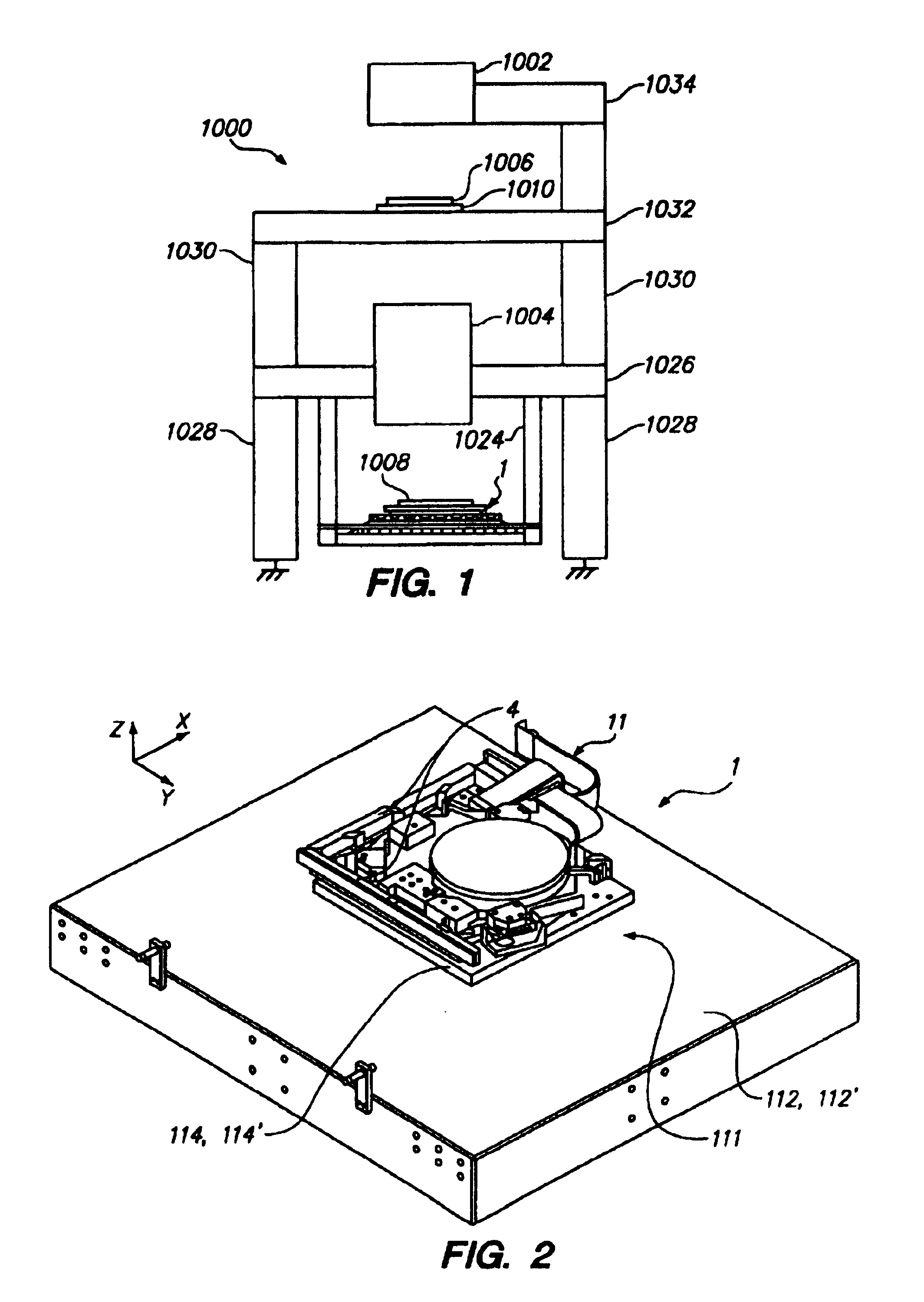
[0058]A brief description of a photolithography instrument will be given here as background for a preferred use of the positioning stage system according to the present invention. FIG. 1 is a schematic view illustrating a photolithographic in...


PUM


Abstract

A positioning stage assembly having a coarse stage which includes a planar motor driveable in at least two degrees of freedom, and a fine stage positioned on the coarse stage which is driveable in at least three degrees of freedom with respect to the coarse stage. More preferably, the fine stage is driveable in six degrees of freedom and includes variable reluctance actuators for positioning in three degrees of freedom.

Description

FIELD OF THE INVENTION[0001]This invention relates to alignment and isolation apparatus and methods for use particularly in microlithography, among other applications. More particularly, this invention is directed to an apparatus with at least a two dimensional motor for coarse stage positioning, in addition to efficient support of a stage for fine alignment in at least three degrees of freedom.BACKGROUND[0002]The need for precise positioning of an object is required in many fields of application, including applications in semiconductor manufacturing such as microlithography. As microprocessors become faster and more powerful, an ever increasing number of transistors are required to be positioned on a semiconductor chip. This necessitates closer placement of the transistors and circuits interconnecting them, which in turn requires an ever increasing accuracy in the methods for laying down the circuits on the chip. Thus, there is a need for more precise positioning and maintaining of...

Claims


Application Information

Patent Timeline
IPC IPC(8): H01L21/68G03B27/42G03F9/00G05B11/16H02K41/00G12B5/00B23Q1/34B23Q1/48B23Q5/28G03F7/20H01L21/027H02K41/03
CPCG03F7/70716G03F7/70758H02K41/03H02K2201/18
Inventor HAZELTON, ANDREW J.NOVAK, W. THOMASEBIHARA, AKIMITSU
Owner NIKON CORP
Why Eureka
Try Eureka