

Wing panels of aeration blower fan
A technology for inflating fans and vanes, which is applied to wind turbines, wind turbine components, engines, etc., can solve the problems of the length of the vanes exceeding the designed camber, the inability to be sent to the installation site, and the large wind-receiving area. Simple structure and material saving effect
- Summary
- Abstract
- Description
- Claims
- Application Information
AI Technical Summary
Problems solved by technology
Method used
Image

Examples
Embodiment 1
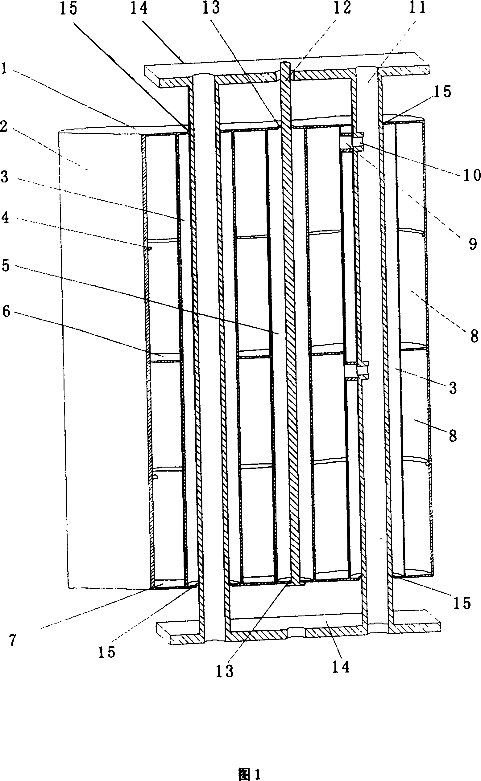
[0017] Embodiment 1, see Fig. 1, inflatable blower airfoil, has airtight wing body of fan airfoil shape, is provided with inflatable air channel in it, is respectively provided with upper wall 1 on the upper and lower part of the airtight housing of fan airfoil shape And the lower wall 7, forms a closed cavity with the streamlined curved side wall 2, and a partition plate 6 is arranged in it, and the inner cavity is divided into two inflatable cavities; two inner holes 3 are arranged in the inflatable cavity , communicating with the through hole 15 on the upper wall 1 and the lower wall 7; two air nozzles 9 are set on the inner hole 3 and communicate with the corresponding inflatable cavity 8. Two support rods 11 are arranged in the inner hole 3, two air valves 10 are arranged on the support rods 11, and communicate with the corresponding air nozzles 9, and the inner hole 5 of a pull wire is also provided in the middle of the inflatable cavity, and the inner hole 5 is arranged ...
Embodiment 2
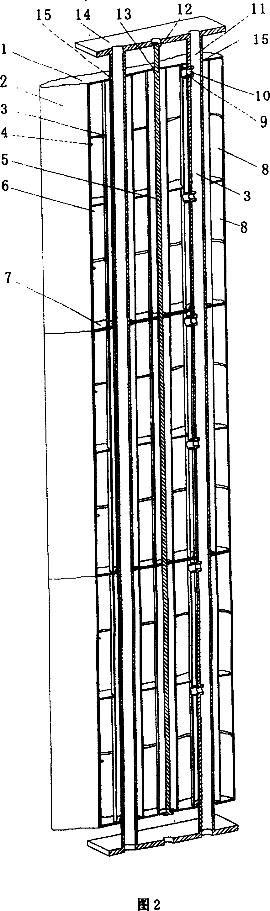
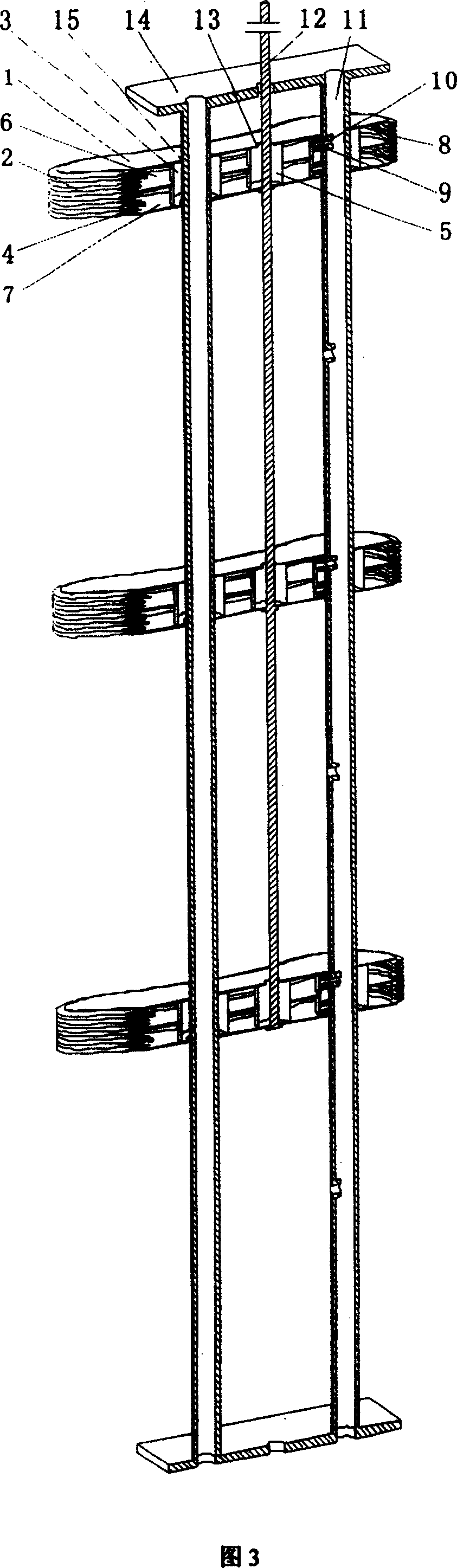
[0018] Embodiment 2, see FIG. 2 and FIG. 3 , an air valve is provided on the support rod 11 to communicate with the corresponding three airtight wing bodies in the shape of fan blades. The structure of each fin is the same as the above-mentioned embodiment. In order to realize that the fins of a large fan can be made by connecting three inflatable fins, the area of the fan fins can be increased, and the power of the fan can be improved. The air blower blade is provided with 2 support rods 11 in the inner hole 3 of the fan blade-shaped airtight wing body, and one of them is provided with 6 air valves 10 to communicate with 6 air nozzles 9 on the inner hole 3 . Also be provided with backguy inner hole 5 in the air-filled cavity, communicate with the through hole on the upper wall 1 and the lower wall 7, be provided with backguy 12 in it, one end is connected with lower wall 7, and the other end is connected with bobbin.
Embodiment 3
[0019] Embodiment 3, see Fig. 4, the upper wing is composed of two closed wing bodies A and B connected in parallel to form a complete wing shape, and connected in series with the lower two closed wing bodies to form a complete wing together.
[0020] The material used in the above three embodiments, the material of the upper wall 1 and the lower wall 7 of the air blower blade of the air blower blade is fiberglass, and the material of the support rod 11 is aluminum alloy. The material of the air blower blade side wall 2 is a flexible chemical fiber material. The inflation gas in the blades of the inflation fan is helium whose specific gravity or density is lower than that of air.
[0021] When in use, inflate through the inner hole of the support rod 11, and each fin can be inflated and connected on site, which can not only solve the transportation problem of the ultra-long fins of large wind turbines at present, but also reduce the manufacturing, transportation and installati...
PUM
 Abstract
Description
Claims
Application Information