
Light-beam offset mechanic apparatus with double light wedges

A beam deflection and mechanical device technology, applied in optics, optical components, nonlinear optics, etc., can solve the problems of high feeding accuracy and dynamic performance requirements of stepping motors, large device volume, large mechanical errors, etc., and achieve overall The appearance is beautiful and compact, the movement is smooth and flexible, and the effect of improving precision

Inactive Publication Date: 2007-10-03
SHANGHAI INST OF OPTICS & FINE MECHANICS CHINESE ACAD OF SCI
View PDF2 Cites 0 Cited by
  • Summary
  • Abstract
  • Description
  • Claims
  • Application Information

AI Technical Summary

Problems solved by technology

[0004] However, the mechanical system of the prior art "Rotary Double Prism Angle Generator" has shortcomings. The rotary stepping motor is directly coupled to the rotating shaft to realize the prism rotation, which requires high feed accuracy and power performance of the stepping motor, and the mechanical error is relatively large.
At the same time, rectangular prisms are used in the prior art, the device is bulky and the structure is not compact

Method used


Image

  • Light-beam offset mechanic apparatus with double light wedges
  • Light-beam offset mechanic apparatus with double light wedges
  • Light-beam offset mechanic apparatus with double light wedges

Examples


Embodiment Construction

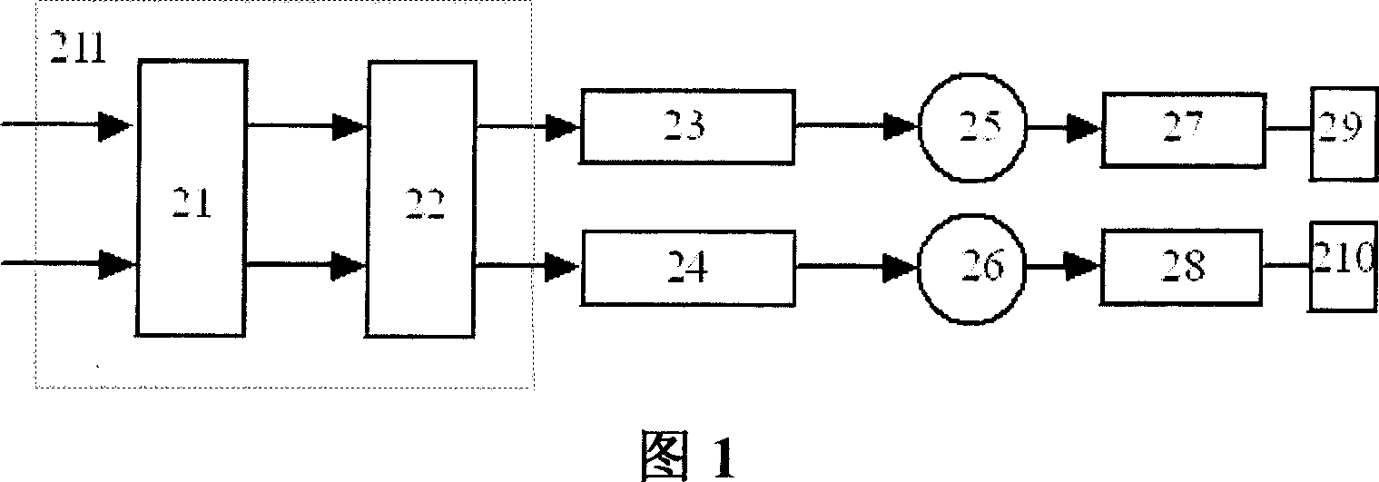
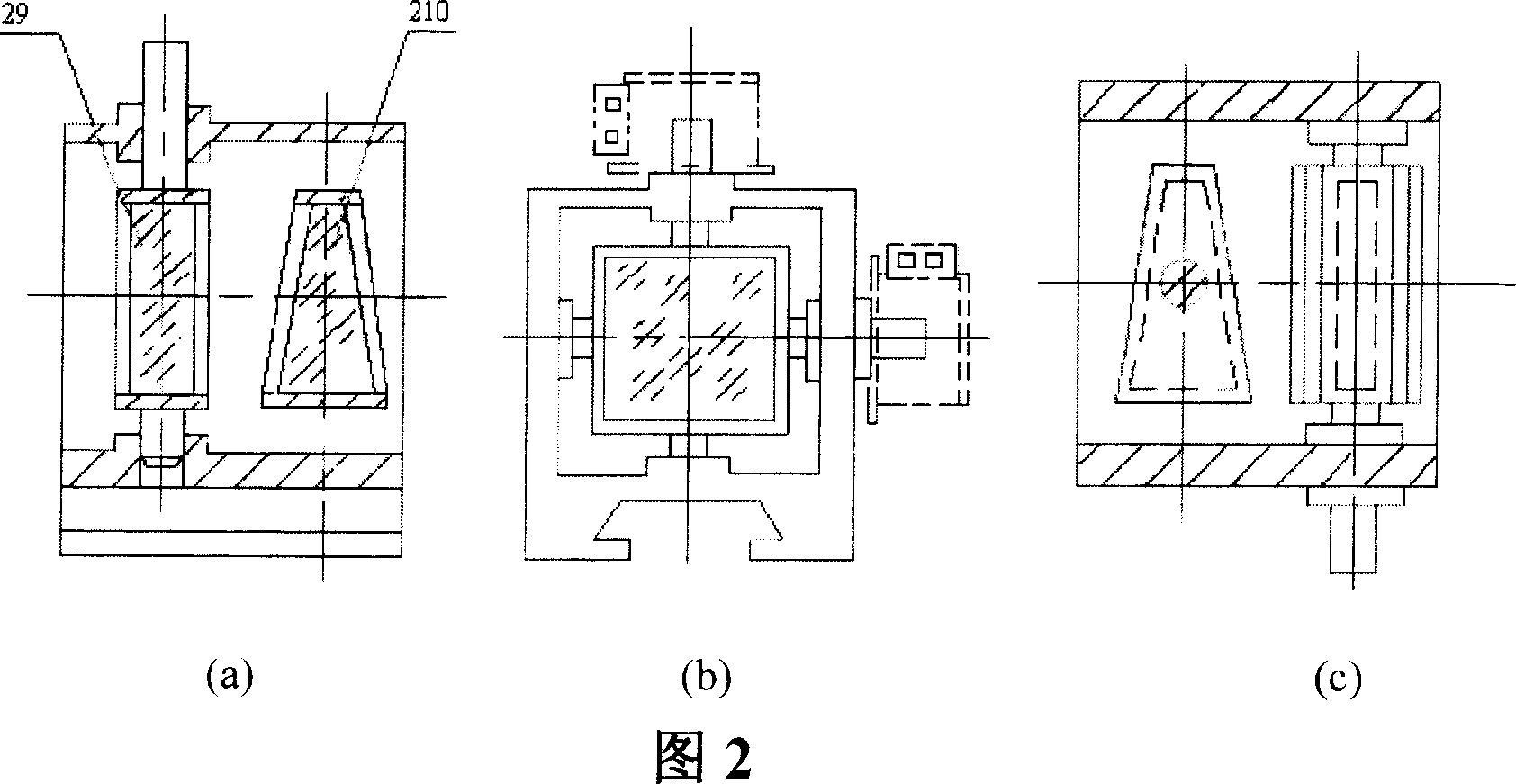
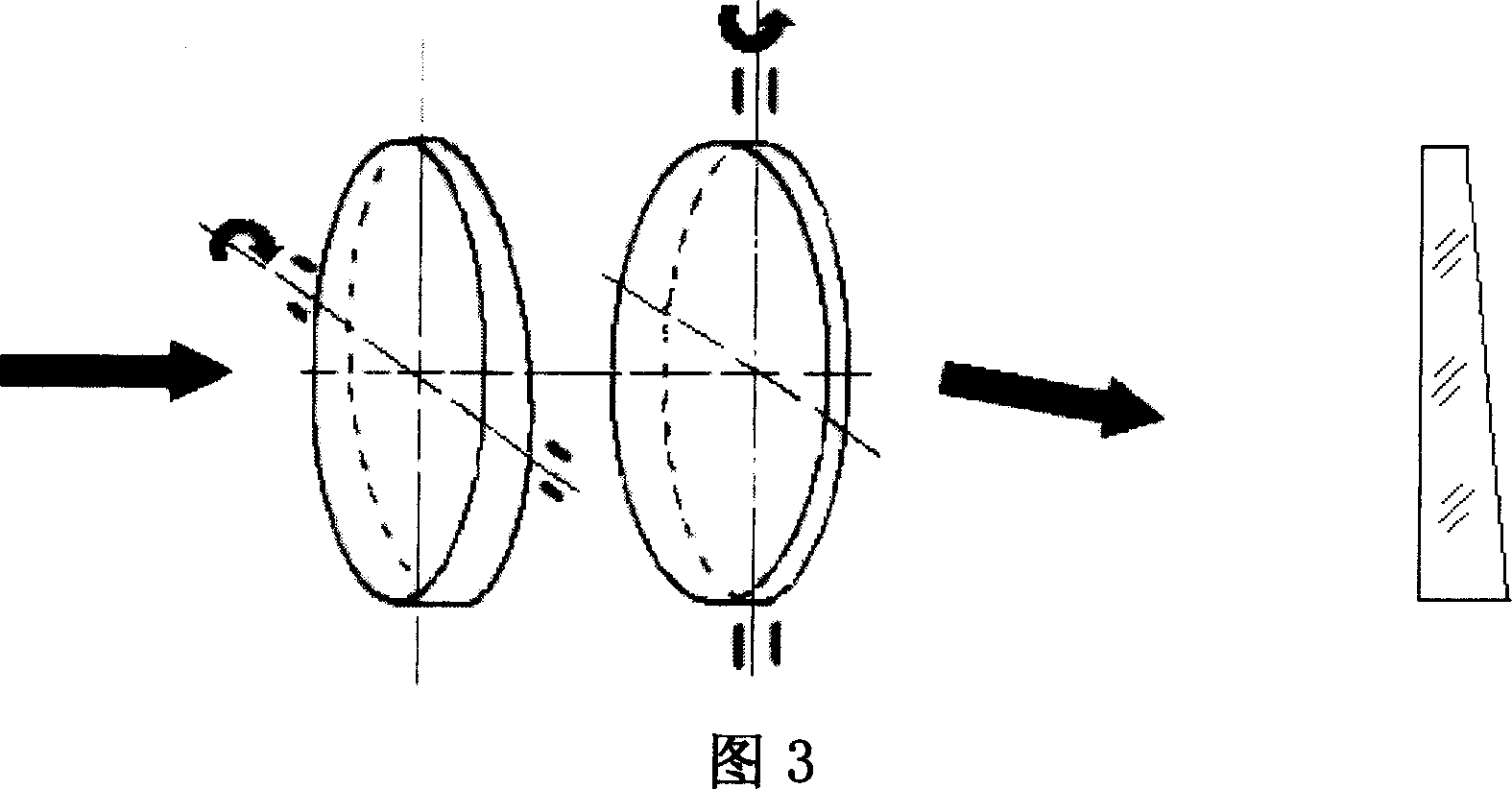
[0026] The present invention will be further described below in conjunction with embodiment. Please refer to Fig. 4 to Fig. 6 first. The double optical wedge beam deflection mechanical device of the present invention comprises a first optical wedge rotating around a horizontal rotation axis, a second optical wedge rotating around a vertical rotation axis, a first linear stepping motor, a second linear stepping motor, a first An angle encoder, a second angle encoder and a base are characterized by:

[0027] The first optical wedge and frame assembly 2 and the second optical wedge and frame assembly 3 are centrally arranged in the base 1:

[0028] The composition of the first optical wedge and the mirror frame assembly 2: referring to Fig. 7, the first optical wedge 21 is glued into the inner lens frame 22, the wedge surface of the first optical wedge 21 is supported by a wedge washer 24, and is passed through O The ring 27 is in contact with the inner mirror frame 22, the inn...


PUM

PropertyMeasurementUnit
diameteraaaaaaaaaa
angleaaaaaaaaaa
angleaaaaaaaaaa

Abstract

A mechanical device of double - wedge beam deflection consists of base, two linear stepping motors, two rails, two round wedges and mirror frames and two angle coders. It is featured as placing vertical and horizontal shafts in orthogonal arrangement with their one end connected on mirror frame and their another supported by bearing, setting two said motors in base to drive two mirror frames to rotate around vertical and horizontal shafts separately and placing angle coder at one side of rotary shaft.

Description

technical field [0001] The invention relates to an optical transmission system, which is a precise double optical wedge beam deflection mechanical device capable of making two circular optical wedges rotate orthogonally in space, and is especially suitable for simulating a certain pitch angle in a small field of view in an optical transmission system and azimuth beam deflection. Background technique [0002] Optical wedges are widely used in optical transmission systems, such as compensators in parallel optical paths (rotating single optical wedges, rotating double optical wedges, swinging dual optical wedges, etc.), compensators in converging optical paths (axially moving single optical wedges , Axial moving double optical wedge, lateral moving double optical wedge, etc.). In practical applications, different optical wedge combinations are used according to different beam deflection angle requirements. Generally, in the parallel optical path, the single optical wedge can ...

Claims


Application Information

Patent Timeline
Patent Type & Authority Patents(China)
IPC IPC(8): G02F1/01G02B27/00
Inventor 李安虎刘立人孙建锋
Owner SHANGHAI INST OF OPTICS & FINE MECHANICS CHINESE ACAD OF SCI
Learn More