Eureka AIR delivers breakthrough ideas for toughest innovation challenges, trusted by R&D personnel around the world.

Cooling and heating system,freezer using said system and automatic vender

A heating system and cooling system technology, applied to cooling and heating systems, can solve the problems of increasing the amount of refrigerant, increasing the risk, increasing the retention of liquid refrigerant, etc., to inhibit the release of moisture and prevent the increase of moisture concentration Effect

Inactive Publication Date: 2007-11-07
PANASONIC CORP
View PDF8 Cites 1 Cited by
  • Summary
  • Abstract
  • Description
  • Claims
  • Application Information

AI Technical Summary

Problems solved by technology

Therefore, the stagnant amount of liquid refrigerant in the connecting pipe is increased, and as a result, the necessary amount of refrigerant for heating is increased.
In particular, in the case of using natural refrigerants with low global warming effect, that is, hydrocarbon refrigerants, the risk of burning at the time of leakage increases

Method used


Image

  • Cooling and heating system,freezer using said system and automatic vender
  • Cooling and heating system,freezer using said system and automatic vender
  • Cooling and heating system,freezer using said system and automatic vender

Examples


Embodiment 1

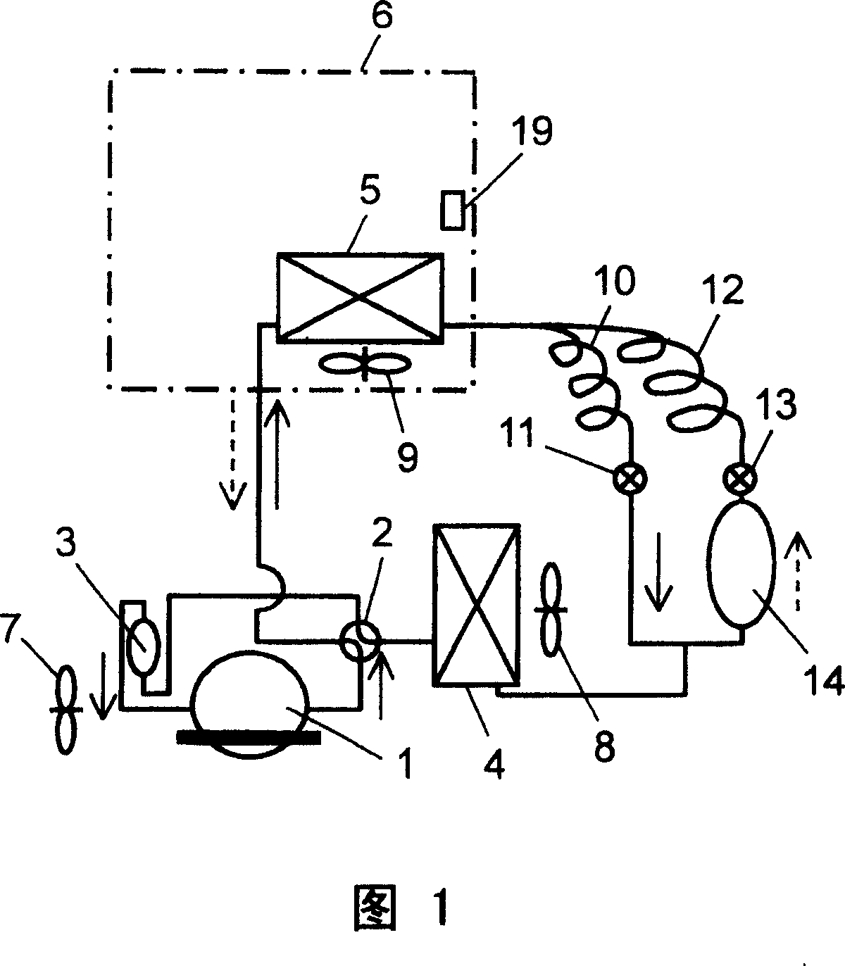
[0028] Fig. 1 is a refrigerant circuit diagram of the cooling and heating system according to Embodiment 1 of the present invention. The cooling and heating system of this embodiment basically consists of compressor 1, four-way valve (hereinafter referred to as valve) 2, accumulator 3, outdoor heat exchanger (hereinafter referred to as exchanger) 4, indoor heat exchanger (hereinafter referred to as Exchanger) 5 and pipes connecting these into a loop. The refrigerating and heating room is composed of such a cooling and heating system and a storage chamber 6 in which the exchanger 5 is arranged. In other words, the accommodating chamber 6 is divided according to the cooling or heating of the exchanger 5. When cooling the inside of the storage chamber 6, the refrigerant discharged from the compressor 1 switches the flow path by the valve 2 and is supplied to the exchanger 5 from the exchanger 4. Then, it passes through the valve 2 again, and returns from the accumulator 3 to the comp...

Embodiment 2

[0081] Fig. 7 is a refrigerant circuit diagram of the cooling and heating system according to Embodiment 2 of the present invention. The refrigerating and heating storage of this embodiment has a storage chamber 6, a compressor 1, an evaporator 5B and a condenser 5A, an evaporator 4A and a condenser 4B, a three-way switching valve (hereinafter referred to as valve) 2A, and a two-way valve (hereinafter referred to as Valves) 11, 13 and dryer 14. The compressor 1, the condenser 4B, the dryer 14, the valve 13, the capillary tube 12, and the evaporator 5B are connected in a ring shape by the first pipe via the valve 2A in the order described above. In addition, the compressor 1, the condenser 5A, the capillary tube 10, the valve 11, and the evaporator 4A are connected in a ring shape by the second pipe through the valve 2A in the order described above. The evaporator 5B and the condenser 5A are installed in the storage chamber 6, and the evaporator 4A and the condenser 4B are installe...

Embodiment 3

[0096] Fig. 9 is a refrigerant circuit diagram of the cooling and heating system according to Embodiment 3 of the present invention. Fig. 11 is a perspective view of the outdoor heat exchanger of this embodiment.

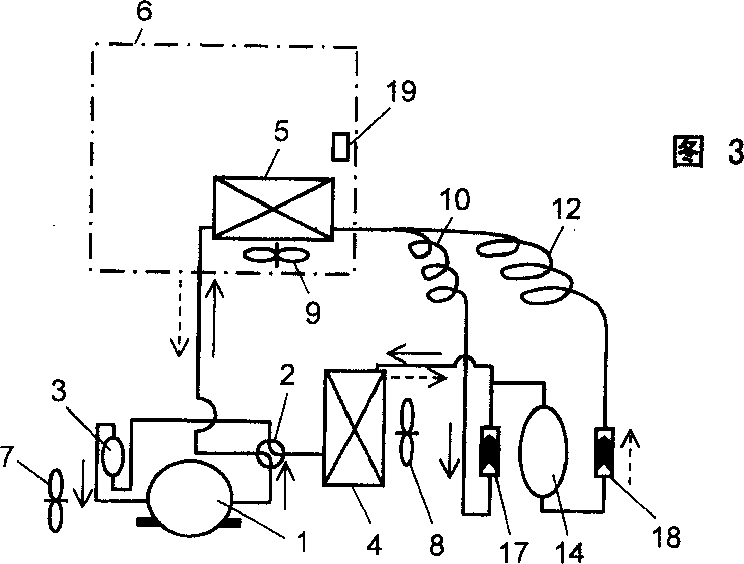
[0097] The cooling and heating system of this embodiment includes a cooling and heating system 51 and a cooling system 52. The basic structure of the cooling and heating system 51 is the same as the structure of FIG. 3 of the first embodiment. In addition, the basic structure of the cooling system 52 is the same as the cooling system shown in FIG. 5. The compressor 1 is installed in a heat-insulating cover (not shown), while being cooled by a fan 7, it is also installed in an indoor heat exchanger (hereinafter referred to as an exchanger) 5, an evaporator 23, an evaporator 24, and an outdoor heat exchanger (hereinafter Fans 8, 41, 42, 62 are independently provided on the switch 61.

[0098]The structure of this embodiment is different from the structure shown in FIG. 5 ...


PUM


Abstract

The present invention relates to a cooling system for cooling and heating the hidden heat produced in condensing the refrigerant compressed by a compressor, as well as a refrigerator using the system and a vending machine for selling canned drinks and other goods after heated or cooled. The present invention uses a plurality of pipelines in parallel connection to connect an expansive mechanism and an outdoor heat exchanger. In addition, when an accommodating chamber is cooled, the pathway of the refrigerant is provided with a pipeline with a drier; when the accommodating chamber is heated, the pathway of the refrigerant is provided with a pipeline besides the pipeline with a drier. Or, in the case of sharing the compressor, a three-way valve is used to make switch between a cooling system for cooling the accommodating chamber with drier in the pathway and a heating system for heating the accommodating chamber without drier in the pathway.

Description

Technical field [0001] The present invention relates to a cooling system that uses latent heat generated when a refrigerant compressed by a compressor is condensed for cooling and heating, as well as a refrigerated heating warehouse using the system, and a vending machine that heats or cools commodities such as canned beverages and sells them. Background technique [0002] In recent years, there has been an increasing demand for reduction in power consumption of refrigeration and heat storage equipment such as merchandise showcases. For this reason, in order to reduce the power consumption when heating with a heater, a technology has been proposed to switch the cooling system to a heat pump for heating in the same manner as in a heating and cooling air conditioner. However, under refrigeration or freezing conditions such as a merchandise showcase, especially when the evaporation temperature is low, the moisture in the refrigerant freezes, which may block the pipe passage. Therefo...

Claims


Application Information

Patent Timeline
Patent Type & Authority Patents(China)
IPC IPC(8): F25B43/00F25B41/04G07F9/10
Inventor 境寿和金城贤治龟井正治平井刚树
Owner PANASONIC CORP
Why Eureka
Eureka Blog
Learn More