Golf club head and manufacturing method thereof

A technology of golf balls and manufacturing methods, which is applied to golf balls, golf clubs, rackets, etc., can solve the problems of increased spacing, reduced overall volume, and impact on the structural stability of golf club heads, and achieves optimal integration and improved The effect of correctness and efficiency

Inactive Publication Date: 2007-12-05
NELSON PRECISION CASTING
View PDF3 Cites 0 Cited by
  • Summary
  • Abstract
  • Description
  • Claims
  • Application Information

AI Technical Summary

Problems solved by technology

However, since the soldering material 34 is powdery before melting, when the soldering material 34 is melted from a powdery solid into a liquid, the total volume of the soldering material 34 shrinks, causing the soldering material 34 to be insufficiently filled in the rods The gap between the head shell 31 and the ball-hitting panel sheet 30 causes gaps that are not completely filled by the welding material 34 to occur between the club-head shells 31 and the ball-hitting panel sheet 30, making the club-head shells 31. The bonding strength between the batting face sheets 30 is relatively greatly reduced, which further affects the structural stability of the entire golf club head
[0010] In order to compensate for the voids caused by the shrinkage of the welding material 34 after melting, the existing joining method adopts the method of increasing the laying amount of the welding material 34 to solve this problem. However, once the laying amount of the welding material 34 increases, the welding material 34 will melt. The total thickness of the welding material 34 that flows into the gap between the club head shell 31 and the ball-hitting face sheet 30 must increase accordingly, but the bonding strength between the head shell 31 and the ball-hitting face plate 30 will not be affected by welding. The thickness of the material 34 is increased and relatively strengthened. On the contrary, because the thickness of the welding material 34 is too thick, the distance between the club head shell 31 and the ball striking panel sheet 30 increases, which further leads to a decrease in the bonding strength of the two. At the same time, the waste of the welding material 34 is also formed. Therefore, how to achieve a balance between the bonding strength and the laying amount of the welding material 34 forms a dilemma.
[0011] In addition, this joining method has produced another problem at the same time, that is, the welding material 34 is directly laid on the shoulder surface 33 of the groove 32, and then is connected to the head shell 31 by the hitting panel sheet 30. At the same time, the groove 32 presses the welding material 34 with the bottom of the ball hitting face sheet 30, so once the joint processing of the head shell 31 and the ball hitting face plate 30 is completed, even if the welding material 34 is insufficiently laid There is a gap between the club head shell 31 and the ball striking panel sheet 30, but the club head shell 31 and the ball striking panel sheet 30 cannot be separated again to increase the laying amount of the welding material 34, and defective products cannot be easily removed. Found to be remedied in the quality control process, therefore, the quality of the product manufactured by this joint method is not good

Method used


Image

  • Golf club head and manufacturing method thereof
  • Golf club head and manufacturing method thereof
  • Golf club head and manufacturing method thereof

Examples


Embodiment Construction

[0041] Before the present invention is described in detail, it should be noted that in the following description, similar elements are denoted by the same reference numerals.

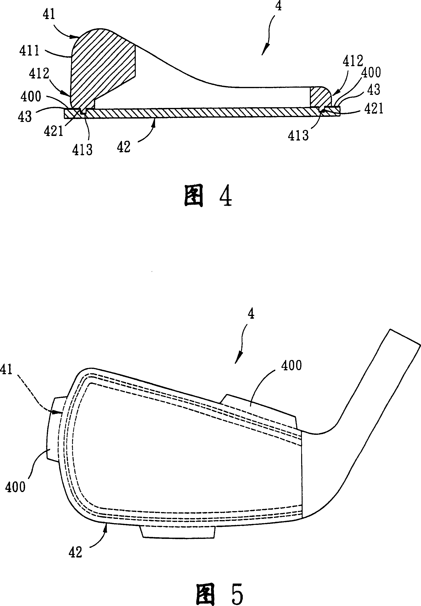
[0042] Referring to FIGS. 4 and 5 , a preferred embodiment of the golf club head 4 of the present invention is an iron club head, including: a shell 41 , a striking panel 42 , and most brazing materials 43 . The shell 41 , the striking panel 42 and the brazing material 43 are all made of different metal materials, and the melting point of the brazing material 43 is lower than that of the shell 41 and the striking panel 42 .

[0043] The housing 41 has a body 411, a joint portion 412 surrounding the periphery of the body 411 (because the joint portion 412 is in a circular shape, so the side sectional view of FIG. 4 shows two joint portions 412), and a The joint portion 412 defines an opening 413 tapering from outside to inside. The striking panel 42 closes the opening 413 of the housing 41 , and a recei...


PUM


Abstract

The golf club head making process includes the steps of preparation, butt jointing, presetting, machining and formation. First, casing, beating panel and hard welding material of different materials are prepared; and then, after the casing and the beating panel are contacted and the hard welding material is set in the holding position of the contact part, the semi-finished golf club head is heated to make the hard welding material flow into the gap between the casing and the beating panel. The present invention can avoid the overflow of the hard welding material, raise the connection strength between the casing and the beating panel and reach better combination performance and raised assembling efficiency.

Description

【Technical field】 [0001] The present invention relates to a club head and its manufacturing method, in particular to a golf club head and its manufacturing method. 【Background technique】 [0002] As shown in FIG. 1 , the combined structure of the shell and the ball striking faceplate of the existing golf wood club head is to expose a hollow shell 10 and a ball striking faceplate 11 . The casing 10 defines an opening 12 . The batting panel 11 is slightly larger than the opening 12 and covers the opening 12 . Wherein, the outer edge of the opening 12 of the housing 10 is provided with an annular convex strip 13, and the back peripheral edge of the hitting panel 11 is provided with an annular groove 14, and the annular convex strips 13 and the groove 14 are mutually fitted. . In addition, there is a welding layer 15 on the mating joint surface of the shell 10 and the ball hitting face plate 11, the welding layer 15 is formed by cooling and solidifying after the melting and i...

Claims


Application Information

Patent Timeline
Patent Type & Authority Patents(China)
IPC IPC(8): A63B53/04A63B102/32
Inventor 陈建同黄峻勇
Owner NELSON PRECISION CASTING
Why Eureka
Try Eureka