
Disk brake

A technology of disc brakes and brake discs, applied in the direction of brake types, mechanical brakes, brake components, etc., can solve the problems of cost increase, complex structure, etc., achieve low wear, single operation mode, and keep wear.

Inactive Publication Date: 2007-12-12
HALDEX BRAKE PROD GMBH
View PDF10 Cites 0 Cited by
  • Summary
  • Abstract
  • Description
  • Claims
  • Application Information

AI Technical Summary

Problems solved by technology

But the structure shown in this invention patent is quite complicated, and the cost increases due to the extra parts that must be designed and produced

Method used


Image

  • Disk brake
  • Disk brake
  • Disk brake

Examples


Embodiment Construction

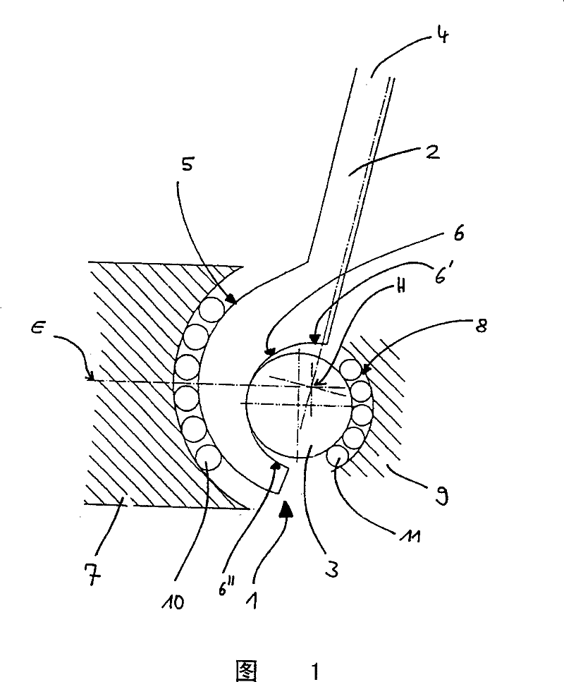
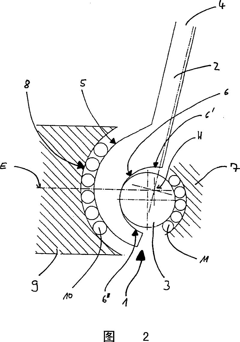
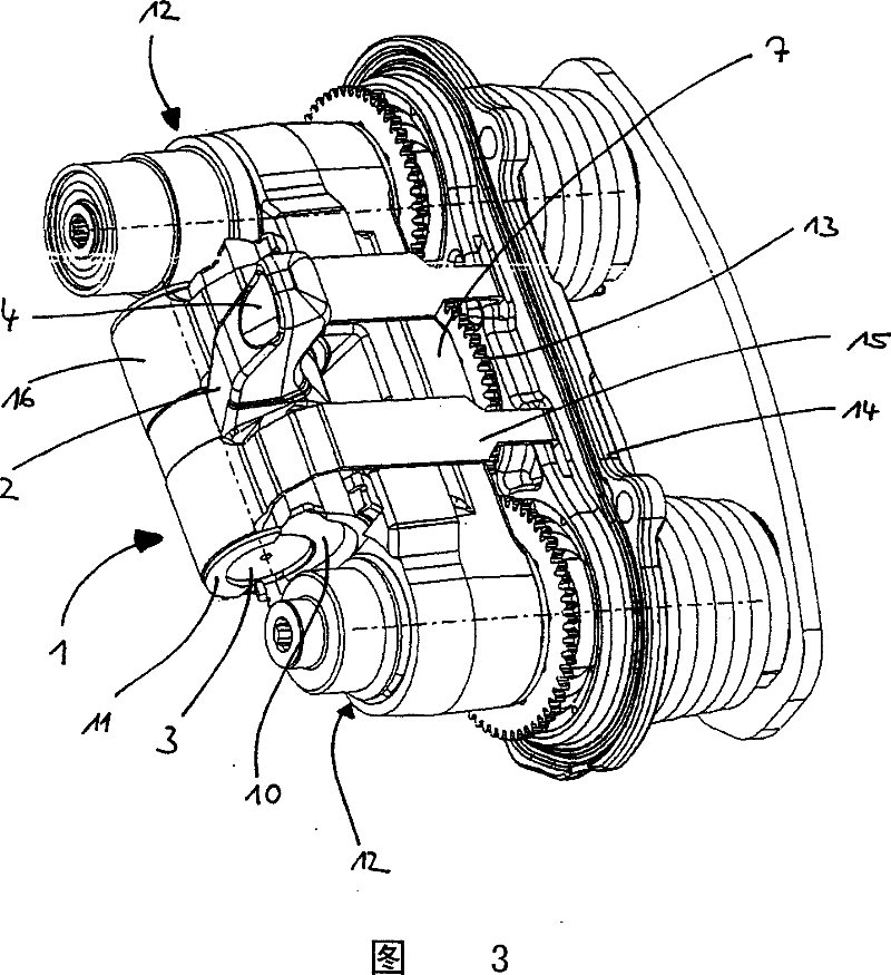
[0037] Figure 1 shows a schematic view of a structure 1 for force transmission between a braking force generating element, such as a hydraulic cylinder (not shown here), and an element transmitting braking force to a brake disc.

[0038] The structural body 1 is substantially composed of a rotating rod 2 and a rotating body 3 .

[0039] The rotary rod 2 has a first support surface 5 remote from its active end 4 , which can be acted on by a piston rod of a hydraulic cylinder, for example. The support surface 3 has a cylindrical hemispherical exterior.

[0040] The control surface 6 is radially opposite the first support surface 5 . On the one hand, the control surface 6 is positioned eccentrically on the first support surface 3 and, on the other hand, it has a concave hemispherical interior.

[0041] The rotating body is in contact with the control surface 6, that is to say that during the braking transmission and rotation of the rotating rod 2, the rotating body 3 purely rol...


PUM


Abstract

The invention relates to a disk brake provided with a brake caliper comprising a brake disk, a sliding member which can be displaced in a vertical manner in relation to the surface of the brake disk in the brake caliper and can be engaged against the brake disk, and a clamping device comprising a rotary lever and a rotational body. In one embodiment of the invention, the rotary lever comprises a domed-shaped control surface whereon the rotational body is arranged in a rotational contact position. By pivoting said rotary lever in a radial segment bearing, the rotational body and the rotary lever modify their position in relation to each other, such that the sliding member is displaced in order to apply braking force. The rotational body then carries out a full rotational movement on the control surface.

Description

technical field [0001] The present invention relates to a disc brake device for a motor vehicle, in particular a heavy-duty vehicle, with a slider which is moved within the brake jaw in a manner perpendicular to the surface of the opposing disc and comes into contact with the disc . The slider is then moved against the brake disc by means of a power transmission comprising a rotary rod. Background technique [0002] The state of the art research includes many conventional means for transmitting force from hydraulic and pneumatic rotating rods to slides or crossbars. [0003] Thereby, as just disclosed in DE2057322C3 patent literature, a kind of starting device that is used for the disc brake that has partial pad. A mechanically actuated brake lever is mounted to rotate within the brake pawl housing via a shaft perpendicular and displaced in the axis of travel of the brake piston. To transmit the mechanical actuating pressure from the brake lever to the slide or brake pist...

Claims


Application Information

Patent Timeline
Patent Type & Authority Patents(China)
IPC IPC(8): F16D65/16F16D65/56F16D55/08F16D65/14
CPCF16D65/183F16D2121/14F16D2125/28F16D2125/32F16C19/502
Inventor L·赛文林森
Owner HALDEX BRAKE PROD GMBH
Learn More