Structure of moving device using electromechanical to control clutch

An electromechanical control and clutch technology, applied in the direction of electric clutches, non-mechanical drive clutches, clutches, etc., can solve the problems of difficult force specifications, changes in action speed and action range, inability to effectively reduce production costs, and reduced service life.

Active Publication Date: 2007-12-19
IND TECH RES INST
View PDF5 Cites 0 Cited by
  • Summary
  • Abstract
  • Description
  • Claims
  • Application Information

AI Technical Summary

Problems solved by technology

[0002] Automated Manual Transmission means that the driver does not need to step on the clutch pedal, but also allows the driver to control the operation of the groove by hand, that is, to drive the clutch to open and close in an automatic control manner. The power source of its automatic control can be operated by a hydraulic cylinder or by an electric motor; in terms of the traditional electric motor, its actuator mechanism is not easy to change the force specification, operating speed and operating range, and its motor The motor needs to be specially designed, and other micro motors (such as window motors and wiper motors) that have been widely used in vehicles cannot be directly used, so that the production cost has not been effectively reduced, and the actuator mechanism is prone to produce lateral force. force component, also leads to reduce its service life

Method used


Image

  • Structure of moving device using electromechanical to control clutch
  • Structure of moving device using electromechanical to control clutch
  • Structure of moving device using electromechanical to control clutch

Examples


Embodiment Construction

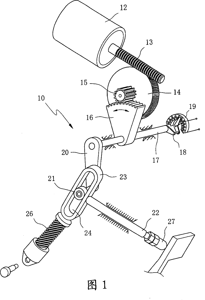
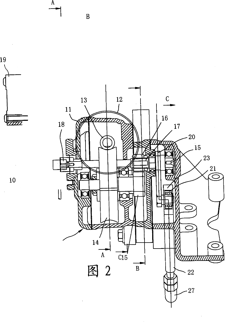
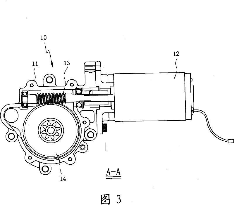
[0021] Please refer to Fig. 1, Fig. 2, Fig. 3, the structure of the actuator 10 of the present invention is that an electric control motor 12 is fixed on the outside of the casing 11, and the rotating shaft of the electric control motor 12 extends into the casing 11 to connect a worm 13, And mesh transmission with a worm gear 14, and utilize the transmission of worm gear set, can obtain very big reduction ratio and enlarge the output torque of electric control motor 12; One side of the rotating shaft is provided with a driving gear 15, which utilizes the rotation of the worm wheel 14 to drive the driven gear 16 meshed with it. The driven gear 16 is placed in order to reduce the excessive space occupied by the casing 11 without affecting the rotation stroke. Made into a fan shape, and this active and passive gear set can carry out the deceleration motion of the second stage; please refer to Fig. 1, Fig. 2, Fig. 3, Fig. 4, Fig. 5, the driven gear 16 is fixed on a rotating shaft 1...


PUM


Abstract

The invention consists of a worm and wormwheel set driven by an electric control motor, a driven gear engaged with a driving gear on the rotation shaft of the wormwheel for driving the rotation shaft of the driven gear to rotate, an oscillating arm firm-jointed at one end of the rotation shaft with a thrust pin. Using the rotation oscillating of the oscillating arm thrusts the pin-lift in the shaft seat to do the linear motion.

Description

technical field [0001] The invention relates to a multi-stage deceleration mechanism, which is especially easy to match with an electric control motor, and converts the rotary motion into a complete linear motion through the crank linkage mechanism, and obtains better thrust value and action speed. The actuator structure of the electromechanical control clutch. Background technique [0002] Automated Manual Transmission means that the driver does not need to step on the clutch pedal, but also allows the driver to control the operation mode of the groove by hand, that is, to drive the clutch to open and close in an automatic control mode. The power source of its automatic control can be operated by a hydraulic cylinder or by an electric motor; in terms of the traditional electric motor, its actuator mechanism is not easy to change the force specification, operating speed and operating range, and its motor The motor needs to be specially designed, and other micro motors (such...

Claims


Application Information

Patent Timeline
Patent Type & Authority Patents(China)
IPC IPC(8): F16D28/00F16H37/12
Inventor 古焕隆魏增德吕俊贤郑丽茹刘丽芬
Owner IND TECH RES INST
Why Eureka
Try Eureka