Method and device promoting gas dissolution through subaqueous aeration
A gas and aeration technology, applied in water aeration, chemical instruments and methods, water/sludge/sewage treatment, etc., can solve the problems of increased maintenance and replacement frequency, aeration blockage, high cost of oxygen supply, etc., to achieve extended Dwelling time, not easy to clog, obvious effect
- Summary
- Abstract
- Description
- Claims
- Application Information
AI Technical Summary
Problems solved by technology
Method used
Image
Examples
Embodiment 1
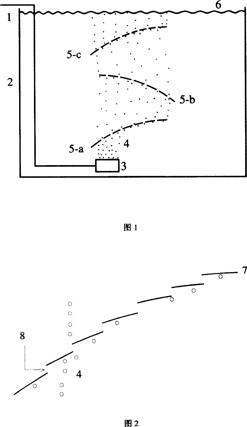
[0022] As shown in Figure 1, the air enters the aeration head 3 installed in the sewage treatment tank 2 through the air pipe 1 to form small air bubbles 4, which rise gradually in an approximate straight line. After encountering the air bubble guide plate 5-a arranged at 1.8 meters above the aeration head, turn to rise in a curve along the guide plate. After rising beyond the upper edge of 5-a, it rises straightly, and when it meets the airflow guide plate 5-b, it turns to rise in a curve along the guide plate. After further rising beyond the upper edge of 5-b, it rises straightly again, and when it encounters the airflow guide plate 5-c, it turns to rise in a curve along the guide plate. After rising beyond the upper edge of 5-c, it rises in a straight line until it emerges from the water 6. In addition, when the bubbles encounter the guide plate, except for some of the bubbles turning to curve upward, the other part of the bubbles pass through the pores of the plate and be...
Embodiment 2
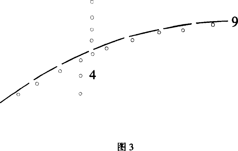
[0024] Figure 2 is a schematic diagram of gas-liquid flow near a bubble deflector. The air bubble guide plate is composed of a plurality of slats in a stepped combination, and there are gaps between each slat, and the distance between the gaps is 30 mm. When the bubble 4 rises and encounters the guide plate 7, it is resisted and becomes a bubble in a curved motion. Due to the deflection of the bubbles, a low-pressure area is formed, which attracts local liquid 8 to flow to the bubble area, forming local mixing of gas and liquid, promoting gas-liquid contact, and increasing gas-liquid mass transfer. In addition, when the bubbles encounter the guide plate, except for some of the bubbles turning to curve upward, the other part of the bubbles pass through the pores of the plate and become rising bubbles. Because the large bubbles are broken when the bubbles pass through the guide plate, the surface area of the gas-liquid contact is increased. At the same time, the distribution...
Embodiment 3
[0026] Fig. 3 is a schematic diagram of gas-liquid flow near another bubble deflector. The bubble guide plate is an upwardly inclined curved panel with long slits, and the distance between the slits is 20 mm (it can also be composed of multiple slats, and there are gaps between each slat. plates do not overlap). When the bubble 4 rises and encounters the guide plate 9, it is resisted, and a part becomes the bubble of the curved motion. The other part passes through the plate holes as rising bubbles. The trajectory of the bubbles moving in a curved line is similar to that of the bubbles in Example 2. The rising air bubbles passing through the plate holes increase the surface area of the gas-liquid contact because the large air bubbles are broken when the air bubbles pass through the guide plate. At the same time, the distribution range of the bubbles is expanded, the gas-liquid contact is promoted, and the gas-liquid mass transfer is increased.
PUM
 Abstract
Description
Claims
Application Information
 - R&D
- Intellectual Property
- Life Sciences
- Materials
- Tech Scout
- Unparalleled Data Quality
- Higher Quality Content
- 60% Fewer Hallucinations
Browse by: Latest US Patents, China's latest patents, Technical Efficacy Thesaurus, Application Domain, Technology Topic, Popular Technical Reports.
© 2025 PatSnap. All rights reserved.Legal|Privacy policy|Modern Slavery Act Transparency Statement|Sitemap|About US| Contact US: help@patsnap.com


