

Punching tool
A technology for drilling tools and drill bits, which can be used in drilling accessories, manufacturing tools, stone processing tools, etc. It can solve problems such as hole blockage, reduce load, reduce the risk of drill loosening, and reduce production costs.
- Summary
- Abstract
- Description
- Claims
- Application Information
AI Technical Summary
Problems solved by technology
Method used
Image

Examples
Embodiment Construction
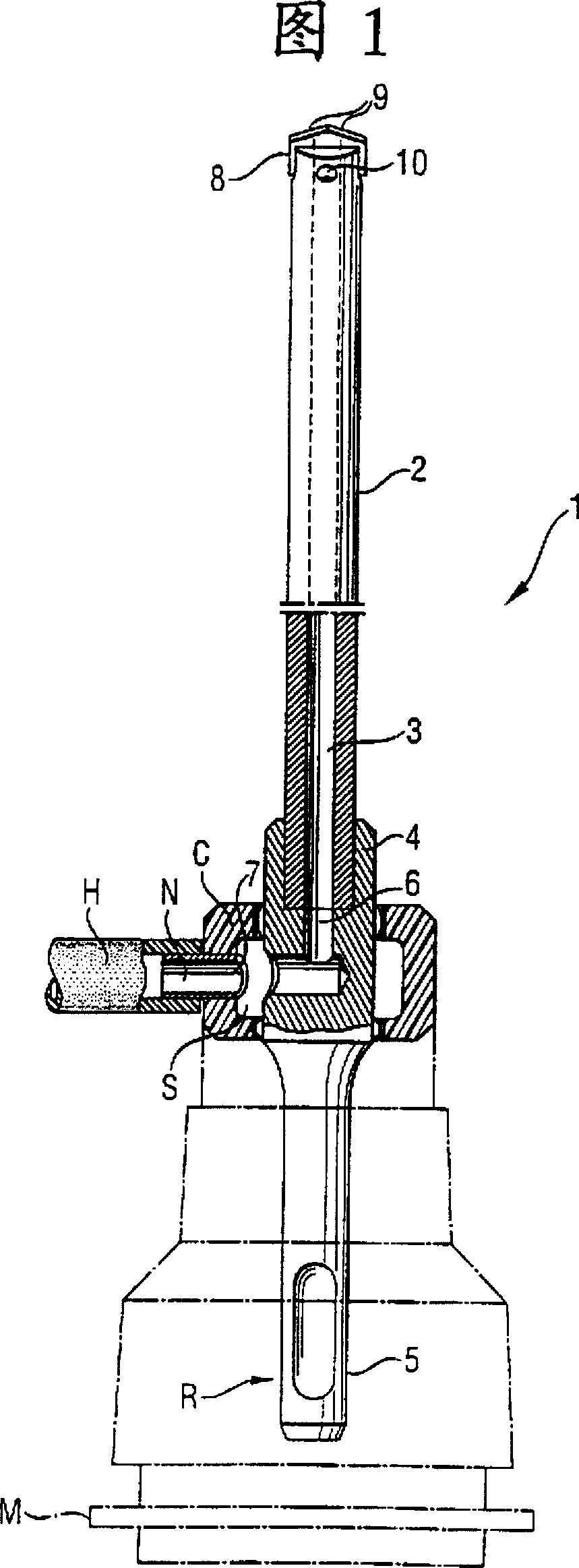
[0030] FIG. 1 shows a drilling tool designed according to the invention, generally designated by the symbol 1, which has been inserted into a tool holder R of a drilling machine M, such as a percussion drilling machine. The drilling tool 1 has a sleeve-shaped shaft 2 with a through hole 3 . The sleeve-shaped rod 2 is connected at one end to a connection part 4, which has a plug-in end 5 for connection in a tool receptacle R of a drilling machine M, for example by soldering. The through hole 3 communicates with a hole 6 in the connection part 4 which opens into a hole 7 at the periphery of the connection part 4 . In the axial extension of the tool mount R, a torsion-transmitting joint C is provided on the drill M, which is equipped with an annular cavity S, which communicates with the outlet hole 7 of the hole 6 in the connection part 4 . The annulus S opens into a connection N, to which the suction hose H is connected. At the end of the sleeve-like rod 2 opposite the connect...
PUM
 Abstract
Description
Claims
Application Information