
Metallurgic slag oxygen ion conductivity cell

A technology of conductivity cell and oxygen ion, which is applied in the field of metallurgy

Inactive Publication Date: 2008-03-12
INNER MONGOLIA UNIV OF SCI & TECH
View PDF4 Cites 0 Cited by
  • Summary
  • Abstract
  • Description
  • Claims
  • Application Information

AI Technical Summary

Problems solved by technology

However, there is no separate conductivity cell for measuring the conductivity of oxygen ions in metallurgical slags.

Method used


Image

  • Metallurgic slag oxygen ion conductivity cell

Examples


Embodiment Construction

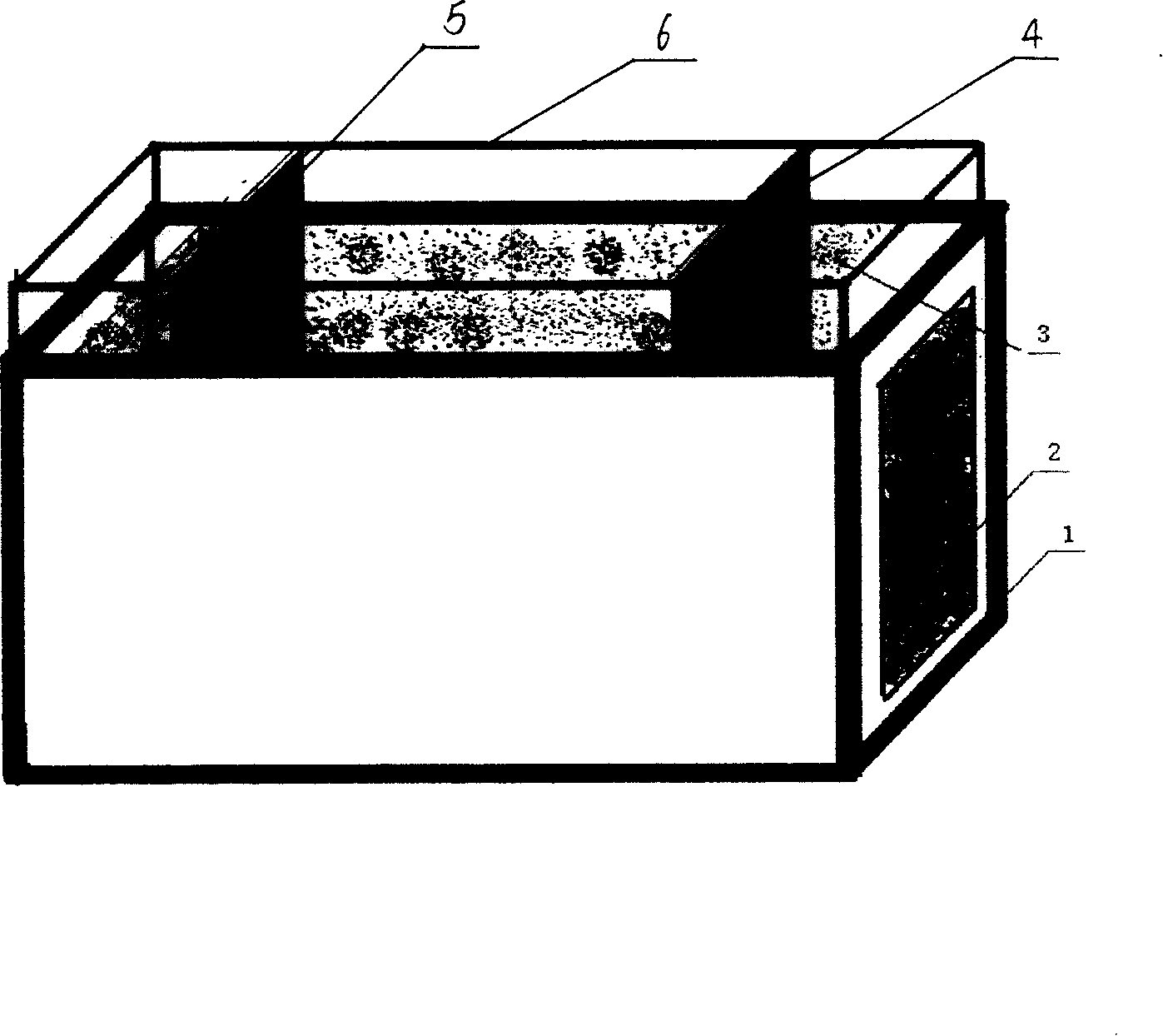
[0007] In the present invention, porous platinum electrodes 2 are respectively installed on both sides of the conductance cell 1 to form the positive and negative poles of the battery. The conductance cell 1 is equipped with molten slag 3, and platinum sheets 4 and 5 are inserted into the molten slag 3 as electrodes for measuring voltage. , above the conductivity cell 1 is provided with a fixed platinum sheet electrode fixing device 6 .

[0008] The two electrodes 2 of porous platinum are symmetrical.

[0009] The fixing device 5 is a ceramic clamp to fix the platinum sheet.

[0010] Use Y 2 o 3 Stabilized ZrO 2 Ultrafine powder is used as raw material, formed by gypsum injection method, fired at 1500°C with length, width and height of 30-50mm, 10-30mm, 10-30mm respectively, and a conductivity cell with a wall thickness of 1-3mm. The platinum acid decomposition method is used to make porous platinum electrodes on the left and right sides, with an area of ​​(10-20)mm×(10-20...


PUM


Abstract

The invention relates to a metallurgical slag oxygen-ion conduction pool for measuring the conductivity rate of oxygen-ion in metallurgical slag under high temperature. The conduction pool employs Y2O3 to steady ZrO2, on the two sides of the conduction pool being pasted with porous platinum electrode to form the positive and negative electrodes of the conduction pool, in the conduction pool containing slag, two platinum chips being inserted in the slag as electrodes for measuring voltage, on the upper space of the conduction pool being provided with a fixation device for fixing the platinum chips.

Description

1. Technical field: [0001] The invention relates to a metallurgical slag oxygen ion conductivity cell, which is used for measuring the conductivity of oxygen ions in the metallurgical slag at high temperature and belongs to the field of metallurgy. 2. Background technology: [0002] At high temperature, oxides in metallurgical slag mainly exist in the state of cations and anions (mainly oxygen ions), so the conductivity of metallurgical slag is the sum of the conductivity of electrons, cations and anions (oxygen ions). At present, the conductivity cell for measuring the conductivity of metallurgical slag can only measure the total conductivity. The electrode is improved, and the electronic conductivity of the slag can be measured by using an ion-blocking electrode. However, there is no separate conductivity cell for measuring the conductivity of oxygen ions in metallurgical slag. 3. Contents of the invention: [0003] The technical problem solved by the invention is: the...

Claims


Application Information

Patent Timeline
Patent Type & Authority Patents(China)
IPC IPC(8): G01N27/07
Inventor 宋希文安胜利赵文广
Owner INNER MONGOLIA UNIV OF SCI & TECH
Learn More