Ac adaptor
A technology of AC adapter and current value, which is applied in current collectors, conversion equipment with intermediate conversion to AC, battery overcurrent protection, etc. It can solve the problems of miniaturization and cost reduction without AC adapter, and the influence of electronic machines.
- Summary
- Abstract
- Description
- Claims
- Application Information
AI Technical Summary
Problems solved by technology
Method used
Image

Examples
no. 1 Embodiment approach
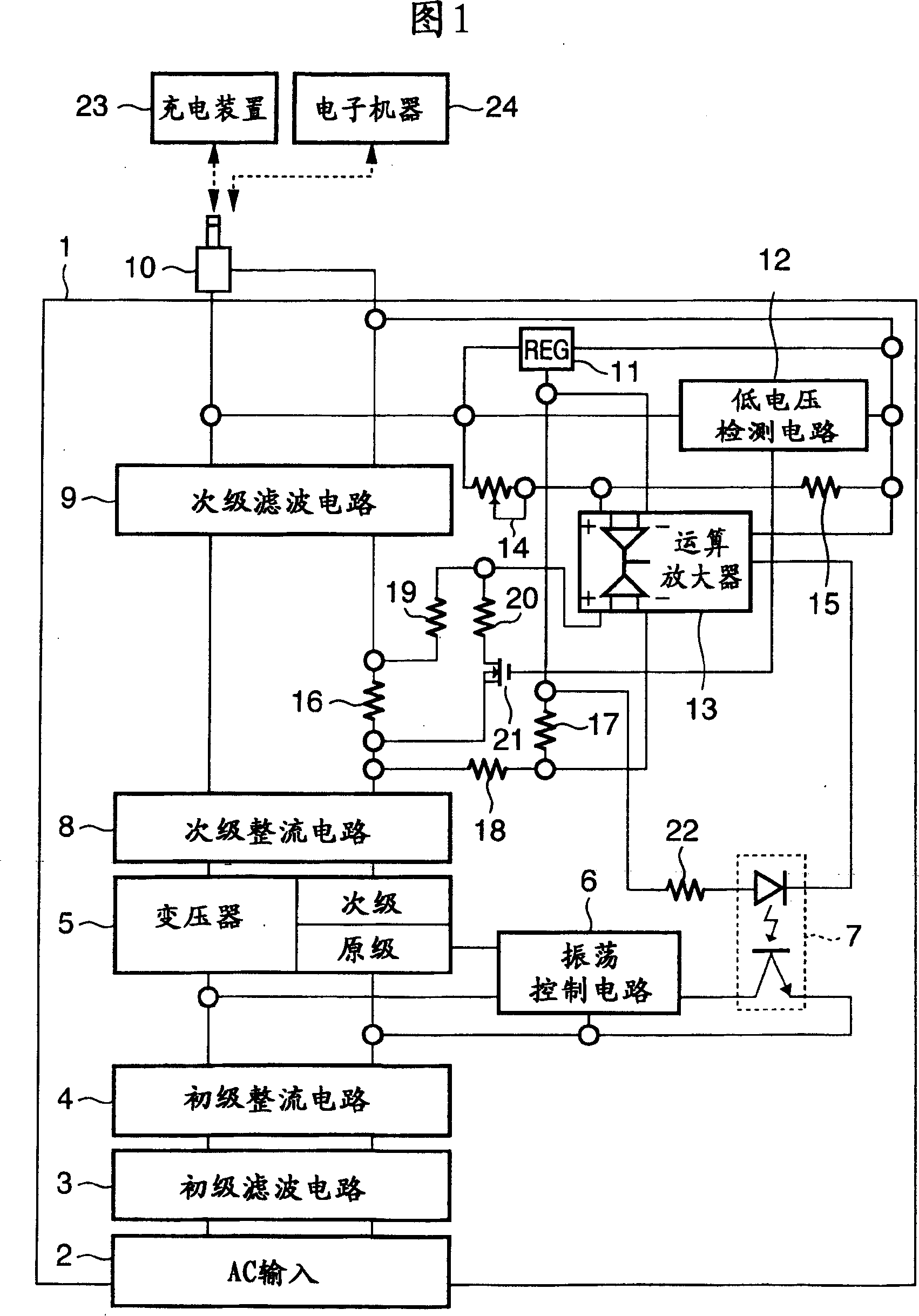
[0019] FIG. 1 is a block diagram most preferably showing the structure of the AC adapter of this embodiment.
[0020] In Figure 1, 1 is the AC adapter, 2 is the AC input part, 3 is the primary filter circuit, 4 is the primary rectification circuit, 5 is the switching transformer, 6 is the oscillation control circuit, 7 is the photocoupler, and 8 is the secondary rectification circuit. Circuit 9 is a secondary filter circuit, 10 is a DC output unit, 11 is a regulator, and 12 is a low voltage detection circuit.
[0021] In addition, 13 is an operational amplifier, 14 is a gain regulator for adjusting the output voltage, 15 is a resistor for dividing the output voltage, 16 is a resistor for detecting the output current, 17 and 18 are resistors for adjusting the output current, 19 20 is a resistor for changing the constant current control value when the output voltage is lower than the value set by the low voltage detection circuit, 21 is a switch for changing the constant current...
no. 2 Embodiment approach
[0039] Fig. 4 shows a second embodiment of the present invention, and is a block diagram showing a configuration example of an AC adapter.
[0040] In FIG. 4 , reference numerals 1 to 24 are the same as those used in FIG. 1 . In FIG. 4, 25 is a temperature detection element, and 26 is a switch. Normally, the above-mentioned switch 26 is in an on state.
[0041]However, when the set value of the constant current is fixed at the second current value for a certain period of time or longer due to an abnormality of the electronic device 24, the internal temperature of the AC adapter 1 rises. Then, when the temperature detection element 25 detects that the preset temperature has been reached, the temperature detection element 25 makes the switch 26 non-conductive. Thereby, the setting value of the constant current is set to the above-mentioned first value, and the internal temperature is lowered.
[0042] By performing such control, it is possible to provide the AC adapter 1 that...
no. 3 Embodiment approach
[0044] Fig. 5 shows a third embodiment of the present invention, and is a block diagram showing a configuration example of an AC adapter. In FIG. 5 , reference numerals 1 to 24 are the same as those used in FIG. 1 .
[0045] In FIG. 5, 27 is a timing circuit. The timer circuit 27 is activated after the setting value of the constant current is set to the second current value due to the inrush current generated in the electronic device 24 . Then, when the inrush current continues for a predetermined time or longer, the timer circuit 27 makes the switch 26 non-conductive. By performing such control, the set value of the constant current is set to the above-mentioned first value.
[0046] As described above, by providing the timing means for measuring the rush current output time of the electronic equipment, it is possible to provide the AC adapter 1 that can safely shut down even when the electronic equipment 24 is abnormal.
PUM
 Abstract
Description
Claims
Application Information
 - R&D
- Intellectual Property
- Life Sciences
- Materials
- Tech Scout
- Unparalleled Data Quality
- Higher Quality Content
- 60% Fewer Hallucinations
Browse by: Latest US Patents, China's latest patents, Technical Efficacy Thesaurus, Application Domain, Technology Topic, Popular Technical Reports.
© 2025 PatSnap. All rights reserved.Legal|Privacy policy|Modern Slavery Act Transparency Statement|Sitemap|About US| Contact US: help@patsnap.com