
Long slope vibratory slipform shaping mill

A molding machine and slope technology, which is applied in the field of long-slope vibrating sliding-form molding machines, can solve the problems of difficult maintenance and repair, complex structure and high cost in the later stage.

Inactive Publication Date: 2008-04-16
耿福明 +1
View PDF3 Cites 3 Cited by
  • Summary
  • Abstract
  • Description
  • Claims
  • Application Information

AI Technical Summary

Problems solved by technology

Its disadvantages are that the structure is very complex, difficult to maintain and repair later, heavy in weight and high in cost

Method used


Image

  • Long slope vibratory slipform shaping mill
  • Long slope vibratory slipform shaping mill
  • Long slope vibratory slipform shaping mill

Examples


Embodiment Construction

[0022] In order to clearly illustrate the technical characteristics of this solution, the following describes this solution through a specific implementation and in conjunction with the accompanying drawings.

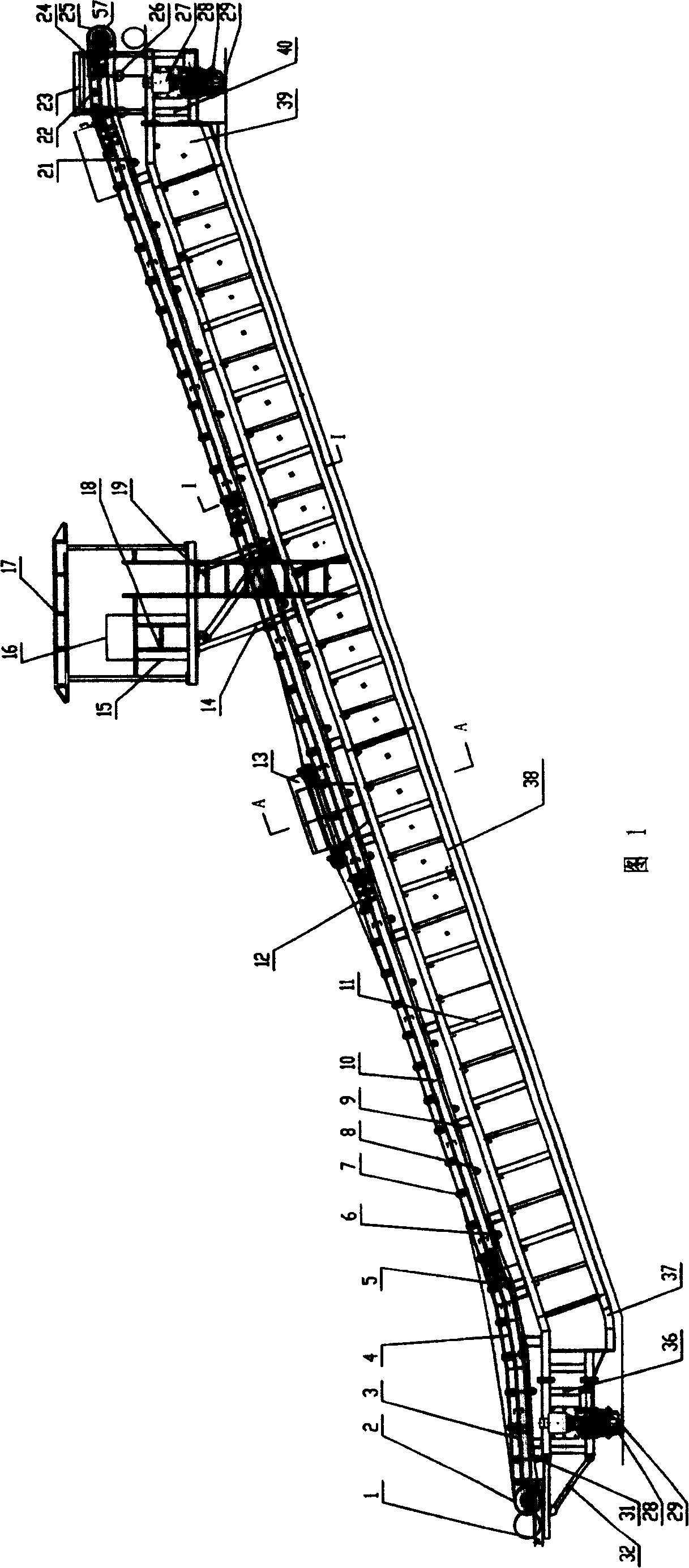
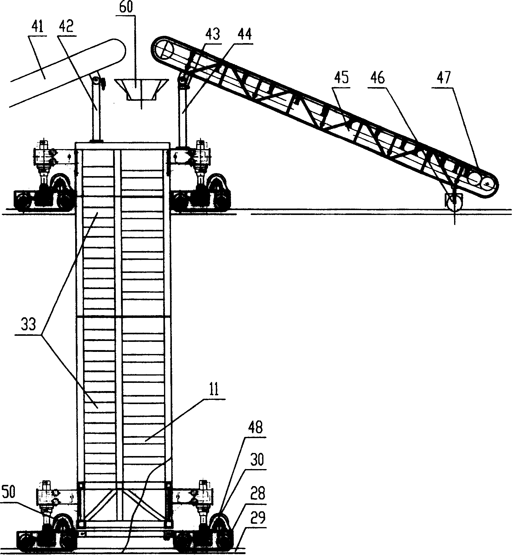
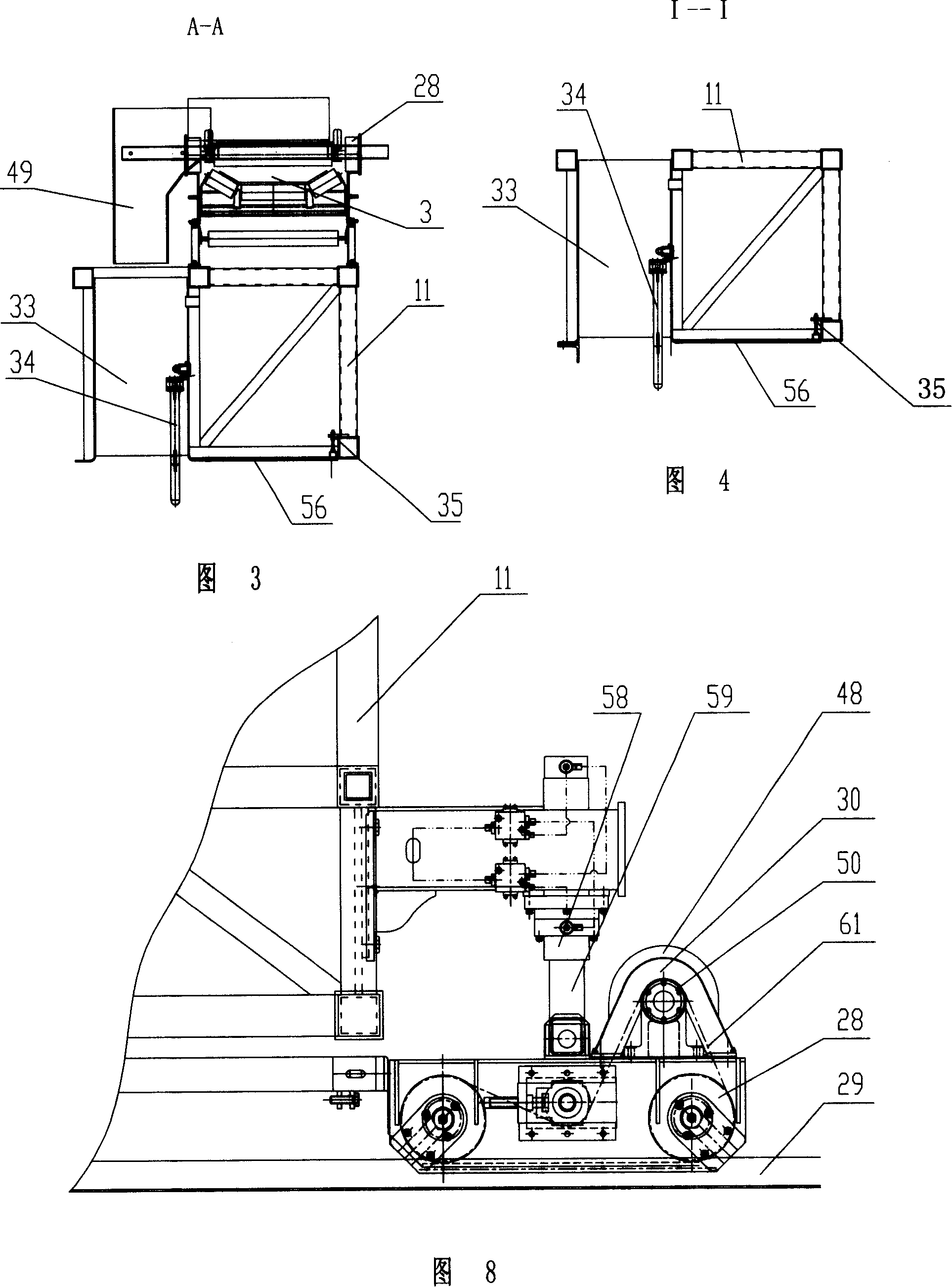
[0023] The present invention is a long-slope vibration sliding mold forming machine, as shown in Figure 1, figure 2 , Figure 4, it includes a cloth device with a walking mechanism, the cloth device includes a frame 11 corresponding to the slope, a cloth conveyor belt 3 is installed on the frame 11, and a movable cloth trolley is set on the cloth conveyor belt 3 13. The distributing trolley 13 is connected to the hoist 57 through a wire rope, and has a control device for the hoist 57. The hoist can specifically adopt a frequency conversion, braking, cycloid or star gear reduction device, all rotating parts are arranged coaxially, and the assembly method is conventional technology . A silo 33 is provided on one side of the cloth conveyor belt 3, an electric vibrating rod 34 ...


PUM


Abstract

This invention relates to long slope resonance module shaping machine in water mechanic filed, wherein the machine comprises Power source, , control device, distribution device with move structure with feeding device. The device is characterized by the following: the distribution device comprises relative racket with cloth transmission band fixed; the band is set with mobile distribution cargo; the distribution transmission band side is set with materials barrel with electrical resonance heads; the cargo has materials bin relative to the one of transmission band. The invention is of simple structure and easy maintenance and of low cost and simple operation.

Description

Technical field [0001] The invention relates to a mechanized channel lining equipment, in particular to a long slope vibrating sliding mold forming machine. Background technique [0002] Mechanized channel lining technology has been developed abroad for decades. At present, the major international manufacturers of large-scale channel lining equipment include Italian MASSENZA, GOMACO, G&Z, RACHO HASSON, and Wetter from Germany. Root (WIRTGEN) company and so on. Most of their products are powered by fuel engines, integrating mechanical, hydraulic and automation. Its shortcomings are: the structure is very complicated, the later maintenance and repair are difficult, the weight is heavy, and the cost is high. Summary of the invention [0003] The technical task of the present invention is to address the shortcomings of the prior art, and provide a simple structure, easy maintenance and repair, light weight, low cost, simple operation and control, low operating costs, high equipment ...

Claims


Application Information

Patent Timeline
Patent Type & Authority Patents(China)
IPC IPC(8): E02B13/00E04G21/02
Inventor 耿福明韩其华朱琳祝凤山贾乃波吕洪勇李树康
Owner 耿福明
Learn More