Worm gear mechanism and electric power steering apparatus equipped with the worm gear mechanism

A worm gear and steering system technology, which is applied in hoisting devices, electric steering mechanisms, portable lifting devices, etc., to achieve the effects of improving durability, improving machining accuracy, and ensuring contact area

Inactive Publication Date: 2008-06-04
HONDA MOTOR CO LTD
View PDF5 Cites 0 Cited by
  • Summary
  • Abstract
  • Description
  • Claims
  • Application Information

AI Technical Summary

Problems solved by technology

[0017] Furthermore, since the rubber O-ring 321 frequently rubs against the tooth tip surface 302b, there is room for further improvement in order to ensure the durability of the rubber O-ring 321.

Method used


Image

  • Worm gear mechanism and electric power steering apparatus equipped with the worm gear mechanism
  • Worm gear mechanism and electric power steering apparatus equipped with the worm gear mechanism
  • Worm gear mechanism and electric power steering apparatus equipped with the worm gear mechanism

Examples


Embodiment Construction

[0064] The best mode for implementing the present invention will be described below with reference to the accompanying drawings. Next, an example in which a worm gear mechanism is mounted on an electric power steering apparatus will be described.

[0065] First, according to Figure 1 to Figure 10 , the first embodiment of the electric power steering device and the worm gear mechanism will be described.

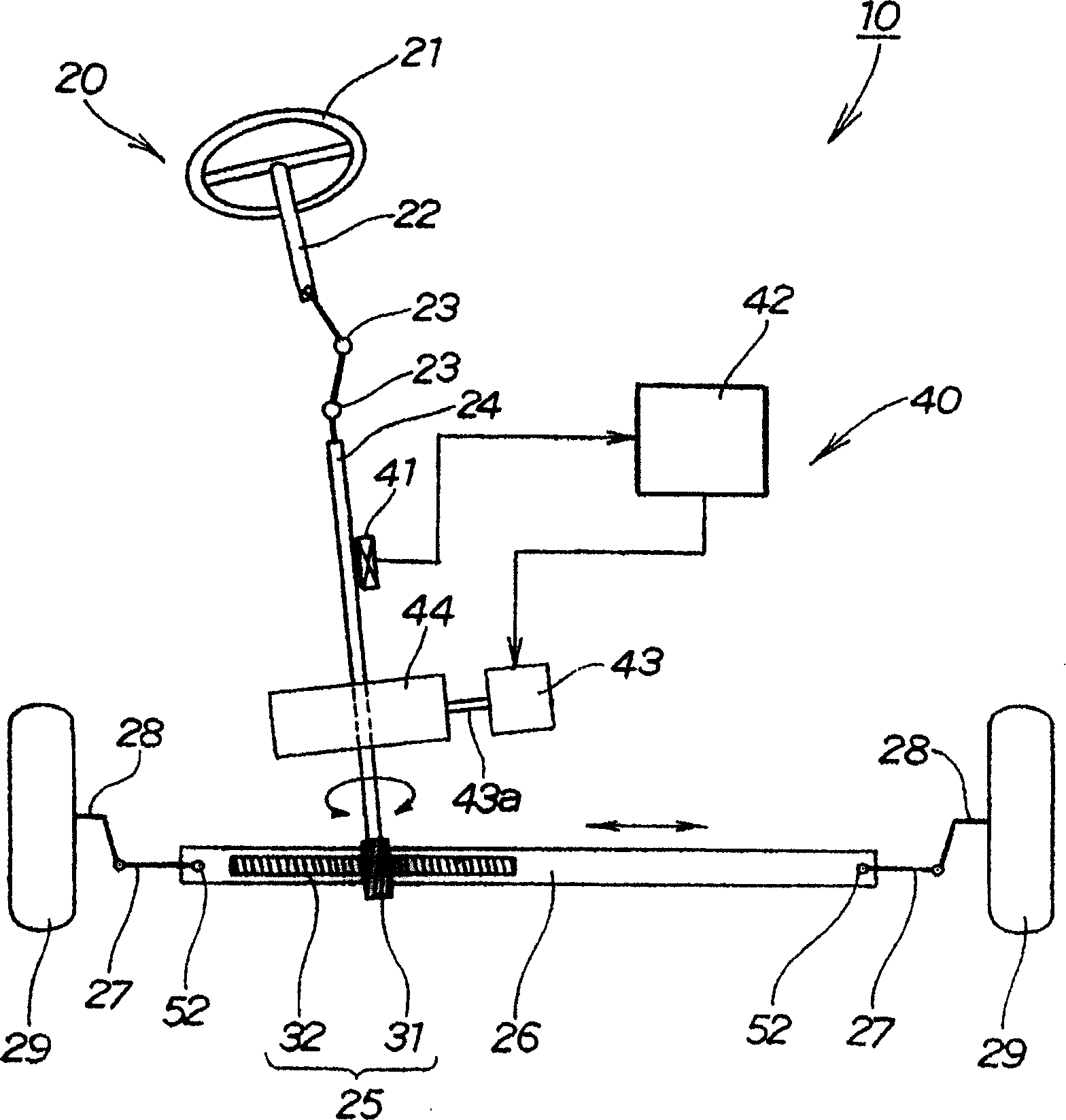
[0066] figure 1 It is a schematic diagram of the electric power steering system (first embodiment) of the present invention. The electric power steering device 10 is composed of a steering system 20 extending from a steering wheel 21 of a vehicle to steered wheels (front wheels) 29 of the vehicle, and an assist torque mechanism 40 for applying assist torque to the steering system 20 .

[0067] In the steering system 20, the pinion shaft (input shaft) is connected to the steering wheel 21 through the universal joints 23, 23, the rack shaft 26 is connected to the pinion sha...


PUM


Abstract

The purpose of this invention is to improve the state of the engagement of a worm with worm wheels by suppressing the hitting noise between the teeth of the worm and the worm wheels to increase the durability of a worm gear mechanism by a simple structure. This worm gear mechanism 44 comprises the worm 47, the worm wheel 48 for torque transmission engaged with the worm, and an auxiliary worm wheel 49 overlapped with the worm wheel for torque transmission. The pitch circle diameter of the auxiliary worm wheel is larger than the pitch circle diameter of the worm wheel for torque transmission. The auxiliary worm wheel is energized to the worm wheel for torque transmission by an energizing member 111 formed of a flat spring.

Description

technical field [0001] The present invention relates to a worm gear mechanism and an electric power steering device equipped with the worm gear mechanism. Background technique [0002] The worm gear mechanism is a transmission mechanism that transmits torque from the worm to the load side via the torque transmission worm wheel by meshing the torque transmission worm wheel with the drive side worm. In such a worm gear mechanism, a technique for suppressing backlash has been developed (for example, refer to Japanese Patent Application Laid-Open No. 2001-355700 (page 3, Figure 1-3 ), Japanese Patent Laid-Open Publication 2002-37100 (page 3, Figure 1-3 )). [0003] use the following Figure 17 Briefly explain the original worm gear mechanism described in Japanese Patent Laid-Open No. 2001-355700, with the following Figure 18 The conventional worm gear mechanism described in JP 2002-37100 A will be briefly described. [0004] Figure 17 (a) to (c) are schematic diagrams (p...

Claims


Application Information

Patent Timeline
Patent Type & Authority Patents(China)
IPC IPC(8): F16H55/24B62D5/04F16H55/22
Inventor 清水康夫渡边胜治青木高大寺田泰浩丰福亮二
Owner HONDA MOTOR CO LTD
Why Eureka
Try Eureka