Socket spot-welding collar pipe fitting for thin wall stainless steel pipe and copper pipe

A technology of stainless steel pipes and plug-in points, which is applied in the direction of pipes/pipe joints/fittings, passage components, mechanical equipment, etc., which can solve problems affecting the tightness of thin tubes and fittings, and achieve the effect of convenient repair and prevention of adverse effects

Inactive Publication Date: 2008-06-04
廖仲力
View PDF2 Cites 0 Cited by
  • Summary
  • Abstract
  • Description
  • Claims
  • Application Information

AI Technical Summary

Problems solved by technology

[0004] The plug-in spot-welding locking pipe fittings of thin-walled stainless steel pipes and copper pipes proposed by the present invention is aimed at solving the above-mentioned effects of the existing compression-type pipe fittings and the Chinese patent 'thin-wall stainless steel plug-in pipe fittings' (ZL200420033074.7) The problem of tightness of thin tube fittings

Method used


Image

  • Socket spot-welding collar pipe fitting for thin wall stainless steel pipe and copper pipe
  • Socket spot-welding collar pipe fitting for thin wall stainless steel pipe and copper pipe
  • Socket spot-welding collar pipe fitting for thin wall stainless steel pipe and copper pipe

Examples


Embodiment 1

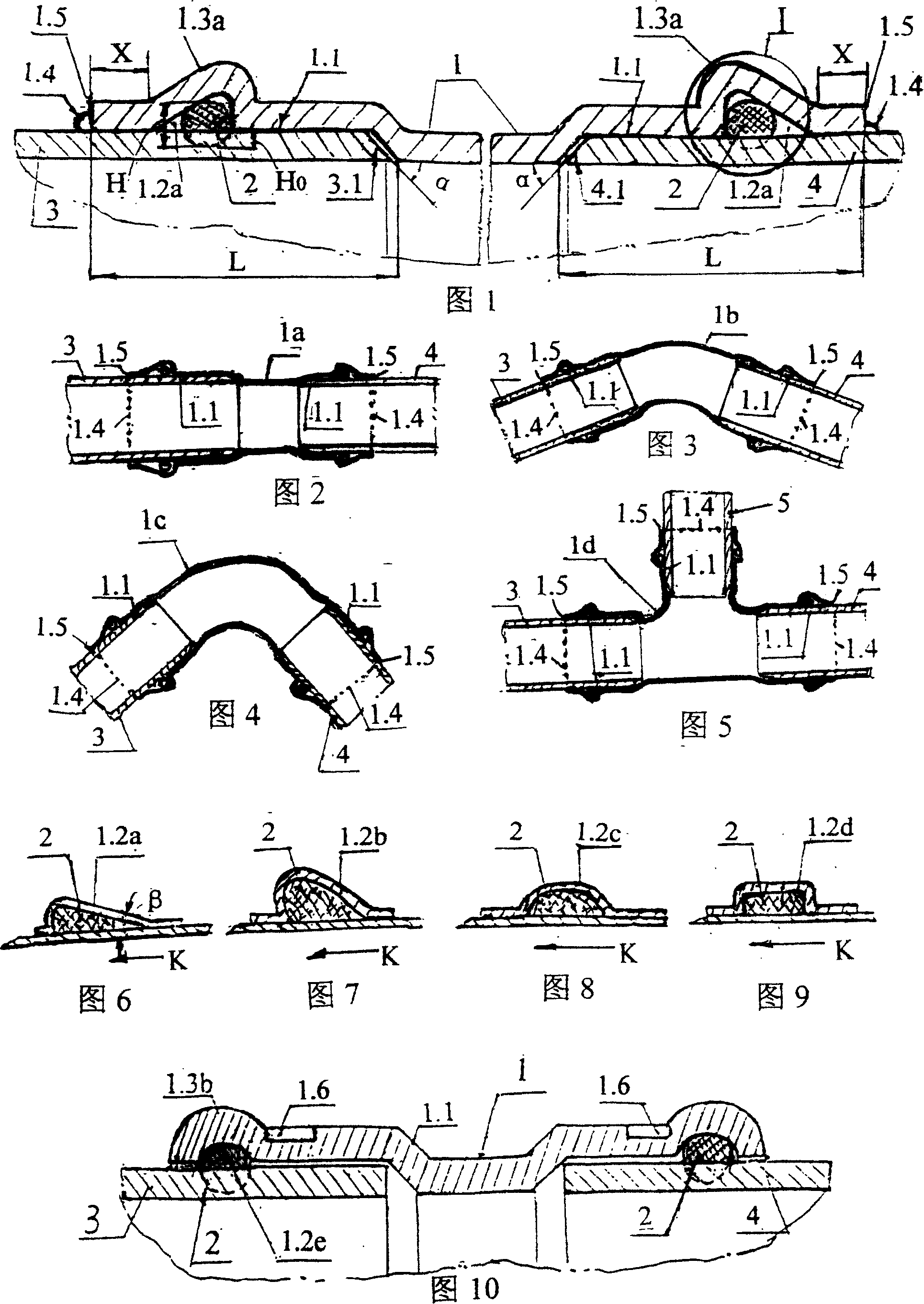
[0033] Embodiment 1: See Fig. 1, this pipe fitting is the straight head that is used for being connected two thin pipes with equal diameter.

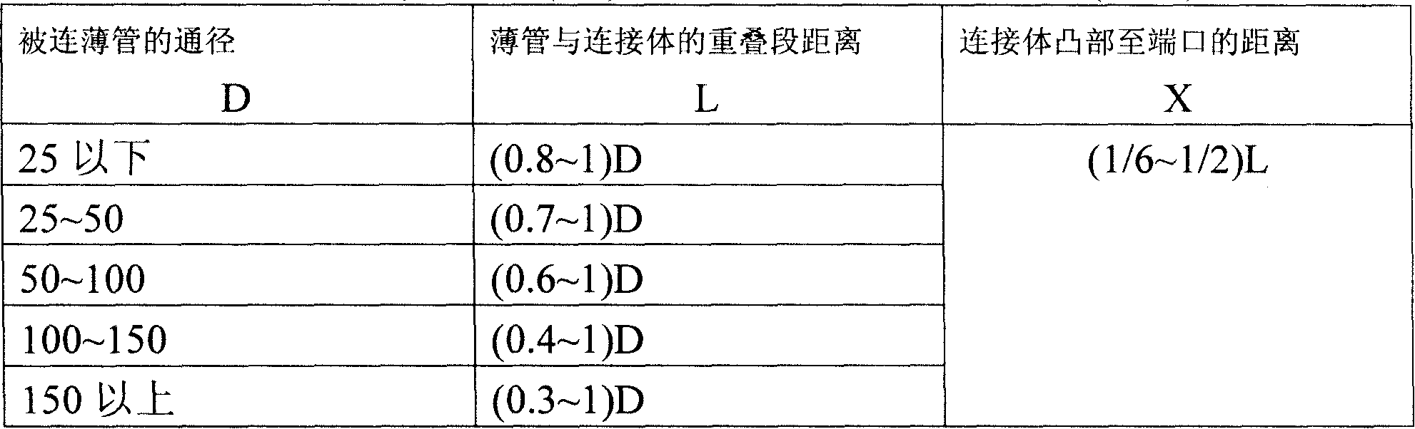
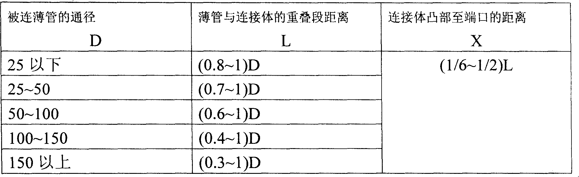
[0034] The pipe fitting is provided with a straight connecting body 1 made of stainless steel, and the inner sides of its two ports 1.5 are a section of reaming section 1.1, and the connected two thin tubes are stainless steel pipes 3 and 4 respectively inserted into the connecting body from the two ports of the straight connecting body hole, and extend to the end of the reaming section 1.1, the overlapping section of the thin tube and the connecting body is L. In the L section, an annular groove 1.2a is opened at both ends of the connecting body hole, and an O-shaped rubber sealing ring 2 is placed in it, so that an annular convex part 1.3 is formed at the corresponding grooves at both ends of the connecting body surface a.

[0035] The two ports 1.5 of the connecting body are respectively connected and fixed with the connected thin t...

Embodiment 2

[0042] Embodiment 2: See Fig. 2, this pipe fitting is the straight head that is used for being connected two thin pipes with different diameters.

[0043] The outer diameter Φ of the connected thin tube 3 is 219mm, and the outer diameter Φ of the thin tube 4 is 159mm. The two thin tubes 3 and 4 to be connected are inserted into the two reaming sections 1.1 in tight fit from the two ports 1.5 of the straight connection body 1a with different diameters respectively. After inserting according to the installation process described in Embodiment 1, 16 flash welding spots are used to complete the 'flash welding lock', each 4 square millimeters, so that the cannula is not pulled out. The rest of the structural shapes and parameters are the same as in Example 1.

Embodiment 3

[0044] Embodiment 3: See Fig. 3, this pipe fitting is the 45 ° elbow that is used to be connected two thin pipes with equal diameter.

[0045] The two connected thin tubes 3 and 4 are inserted into the two reaming sections 1.1 with tight fit from the two ports 1.5 of the 45° elbow connection body 1b respectively. For example: the outer diameter of the thin tubes 3 and 4 is 219mm, and there are 16 flash welding spots, each of which is 4 square millimeters. The rest of the structural shapes and parameters are the same as in Example 1.


PUM


Abstract

The invention is a plugging spot welding collar pipefitting of thin wall stainless steel pipe and copper pipe. The connected thin pipe ends are grooved and separately tightly matched and inserted into from every end of the connecting body. Sealing washers and grooves are set in matched section. Protrudes are formed at surfaces. Flash welding collar is used between ends and thin pipes. It not only guarantees the needed pull-off force, but also can cut-welding spot extract pipe to repair it conveniently during the pipeline is reequipped.

Description

(1) Technical field: [0001] Thin-walled stainless steel pipe and copper pipe socket spot welding lock fittings, which belong to engineering component pipe fittings (F16L). The scope of application is thin-walled stainless steel pipes with a diameter of 15-200mm and copper pipes with a diameter of 15-50mm. (two) background technology: [0002] Existing published clamping type pipe fittings for thin-walled stainless steel pipes, its structure is shown in Fig. In the reaming section, an annular semicircular groove 1.2e and an O-ring seal 2 are arranged at the port, and an annular convex portion 1.3b is formed on the surface. During installation, the surface of the connecting body inside the convex part is pressed with a pressing mold and hydraulic tools to form a hexagonal prism 1.6, and the connecting body, thin tube and sealing ring are pressed and deformed into one, thus forming a compression seal. This kind of clamping pipe fittings has the following problems: ①Eccentrici...

Claims


Application Information

Patent Timeline
Patent Type & Authority Patents(China)
IPC IPC(8): F16L25/00
Inventor 廖仲力
Owner 廖仲力
Why Eureka
Try Eureka