Optical film and polarizing film using the same, and method for improving view angle of the polarizing film

A technology of optical film and polarizing element, applied in optics, polarizing element, nonlinear optics, etc., can solve the problem of polarizing element or polarizing film viewing angle dependence, light leakage, absorption of polarizing film on the exit side, etc.

Inactive Publication Date: 2008-06-11
NIPPON KAYAKU CO LTD +1
View PDF11 Cites 1 Cited by
  • Summary
  • Abstract
  • Description
  • Claims
  • Application Information

AI Technical Summary

Problems solved by technology

[0004] However, when two such polarizing elements or polarizing films are arranged so that their respective absorption optical axes are perpendicular to each other, because the polarized light passing through the incident polarizing element or polarizing film cannot be sufficiently absorbed by the outgoing polarizing film, when the observation point When tilted from the front to a direction deviated from the respective axis directions, light leakage occurs, so-called viewing angle dependence of polarizing elements or polarizing films

Method used


Image

  • Optical film and polarizing film using the same, and method for improving view angle of the polarizing film
  • Optical film and polarizing film using the same, and method for improving view angle of the polarizing film
  • Optical film and polarizing film using the same, and method for improving view angle of the polarizing film

Examples


example 1

[0091] The solution that the solid fraction concentration is 20% is by in the mixed solvent of the toluene of 300 parts by weight and the cyclohexanone of 100 parts by weight, dissolves 23.5 parts by weight and 70.5 parts by weight respectively shown in chemical formula (1) and (2) The UV-curable liquid crystal compound described in WO97 / 44703, and a mixture of 6 parts by weight of photopolymerization initiator Irga-cure 907 (Ciba Specialty Chemicals Company) were prepared.

[0092] (chemical formula 1)

[0093]

[0094] (chemical formula 2)

[0095]

[0096]The solution was applied on the polarizing element side of an iodide-based polarizing film manufactured by Polatechno Corporation (15% borate content in polyvinyl alcohol having a degree of polymerization of 1700 and a thickness of about 20 μm after stretching; A polyvinyl alcohol film was bonded to one side of a cellulose triacetate film treated with an alkali as a surface layer of a protective film by using a poly...

example 2

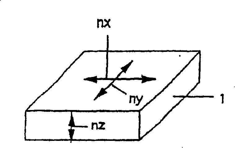
[0098] Polarizing film of the present invention obtains with the same method as example 1, except a piece of polarizing film, or polycarbonate film, uses PSA to be used in the polarizing film of example 1 (Δn p d p =39nm) of the first retardation film surface is laminated so that n x The direction is aligned with the direction of the absorption optical axis of the polarizing element. The refractive index n of the second retardation film in the direction showing the maximum in-plane refractive index x is 1.5864, the refractive index n in the direction perpendicular to the direction just mentioned y is 1.5844, the refractive index n in the thickness direction z is 1.5841, the thickness d is 70μm, and at 550nm (n x -n y )·d is 140nm. This polarizing film was bonded to the iodide-based polarizing film (manufactured by Polatechno Corporation) used in Example 1 with PSA so that the absorption optical axes of the polarizing elements were perpendicular to each other. The polari...

example 3

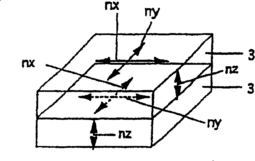
[0100] The first retardation film (Δn) prepared by the same procedure as in Example 1 p d p = 65 nm) was bonded to the third retardation film, or a cellulose triacetate film having an adhesive film layer on one side and the surface layer was treated with alkali, and the first retardation film was peeled off from the polarizing element. The refractive index n of the cellulose triacetate film in the direction showing the maximum in-plane refractive index x is 1.49522, the refractive index n in the direction perpendicular to the direction just mentioned y is 1.49517, the refractive index n in the thickness direction z (n e ) is 1.49461, thickness d n 80μm, average in-plane refractive index n 0 is 1.49520, in relation n e -n 0 =Δn n Down, |Δn n dn n | is 49nm. Then, the second retardation film, or used in Example 1 at 550nm (n x -n y ) A polycarbonate film whose d is 140 nm is laminated with PSA on the first retardation film side of the laminated structure of the peel...


PUM

PropertyMeasurementUnit
thicknessaaaaaaaaaa
thicknessaaaaaaaaaa
thicknessaaaaaaaaaa

Abstract

An optical film, comprising a first phase contrast film (2) having a requirement of (ne - no > 0) where an average refractive index in the surface of at least one sheet of film is (no) and a refractive index in the thickness direction thereof is (ne) and a second phase contrast film (3) having a requirement of (nx > ny > / = nz) where a refractive index in the surface of at least one sheet of film in the direction providing the maximum refractive index is (nx), a refractive index in the direction perpendicular to that direction is (ny), and a refractive index in the thickness direction thereof is (nz), wherein both films are laminated with each other, whereby, when the absorbing axis directions of a polarizing plate are disposed perpendicular to each other, the leakage of light occurred when an observing direction is tilted from a front in a direction different from the absorbing axis directions can be reduced.

Description

[0001] This application is the application date: 2001.12.17, the application number is 01820781.2 (the international application number is PCT / JP01 / 11029), and the name is "optical film, polarizing film using the optical film and method for improving the viewing angle of the polarizing film" divisional application. technical field [0002] The present invention relates to a polarizing film and a retardation film for a liquid crystal display device. Background technique [0003] A polarizing film used as an essential optical component of a liquid crystal display device is obtained by disposing a polarizing element between protective films such as a cellulose triacetate film whose surface layer has been treated with an alkali using an adhesive. The polarizing element is achieved by, for example, uniaxially aligning a film of polyvinyl alcohol dipped in a water-soluble dichroic dye or dichroic pigment such as polyiodide ions in a warm aqueous solution of boric acid, and by unia...

Claims


Application Information

Patent Timeline
Patent Type & Authority Patents(China)
IPC IPC(8): G02B5/30G02F1/1335
Inventor 田中兴一
Owner NIPPON KAYAKU CO LTD
Why Eureka
Try Eureka