External-rotating permanent magnet motor

A permanent magnet motor, external rotation technology, applied in synchronous motors with static armatures and rotating magnets, magnetic circuit rotating parts, magnetic circuit shape/style/structure, etc., can solve the problem of insufficient strength, permanent magnet sticking With problems such as unreliable positioning, it can achieve the effect of improving braking efficiency, stable strength and easy installation.

Inactive Publication Date: 2008-06-25
YUNG TAY ENG
View PDF5 Cites 0 Cited by
  • Summary
  • Abstract
  • Description
  • Claims
  • Application Information

AI Technical Summary

Problems solved by technology

[0005] The technical problem to be solved by the present invention is to provide an externally rotating permanent magnet motor, which solves the problems of unreliable attachment and positioning of permanent magnets in the prior art, and insufficient strength when resisting the tangential force of the motor operation.

Method used


Image

  • External-rotating permanent magnet motor
  • External-rotating permanent magnet motor
  • External-rotating permanent magnet motor

Examples


Embodiment Construction

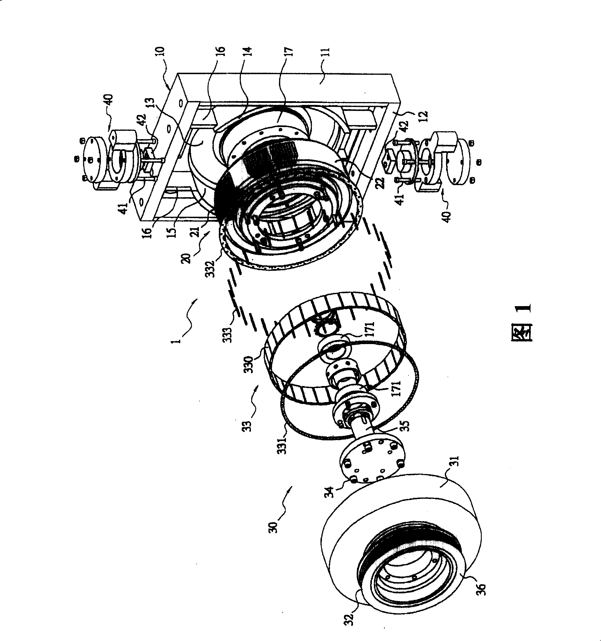
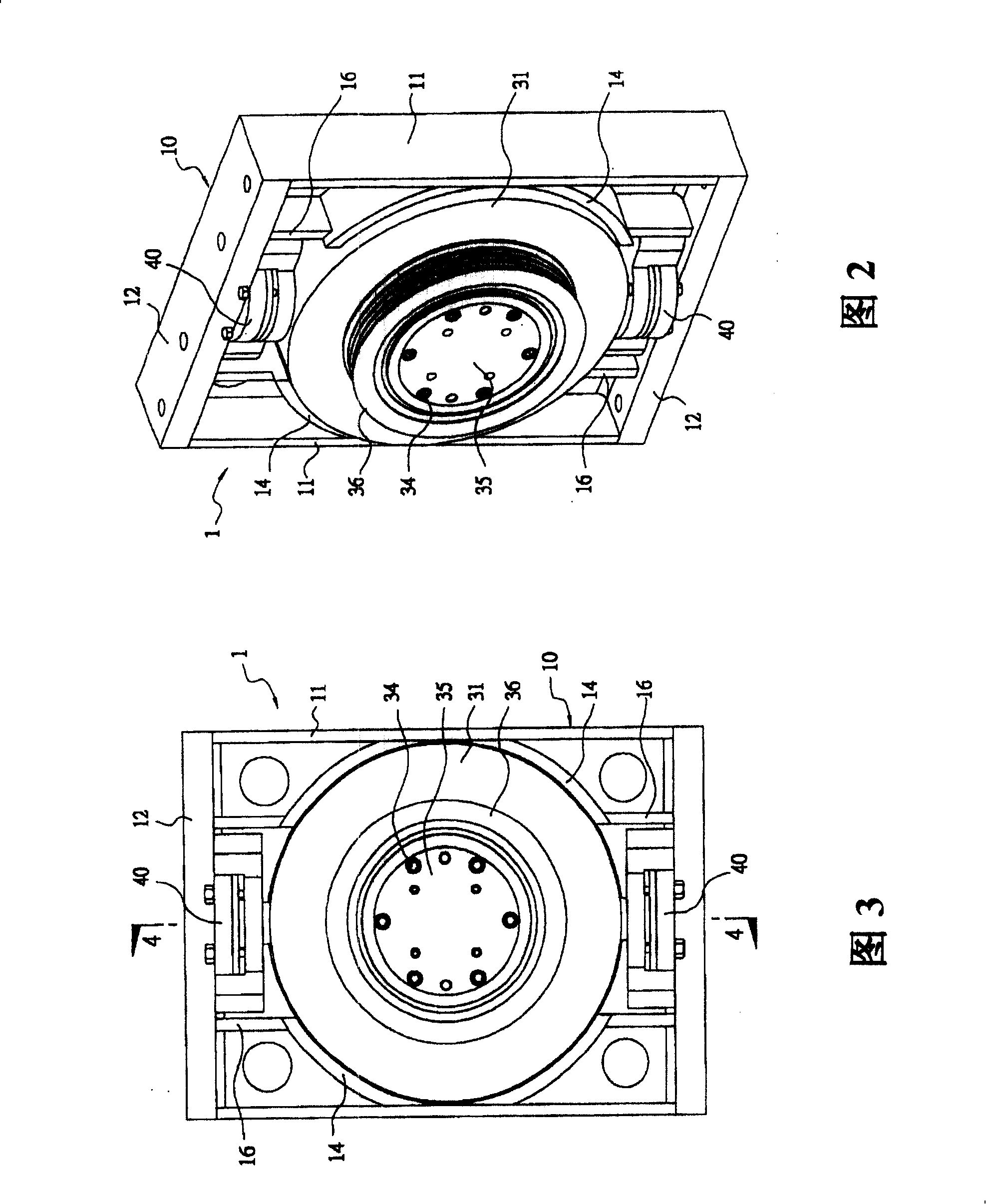
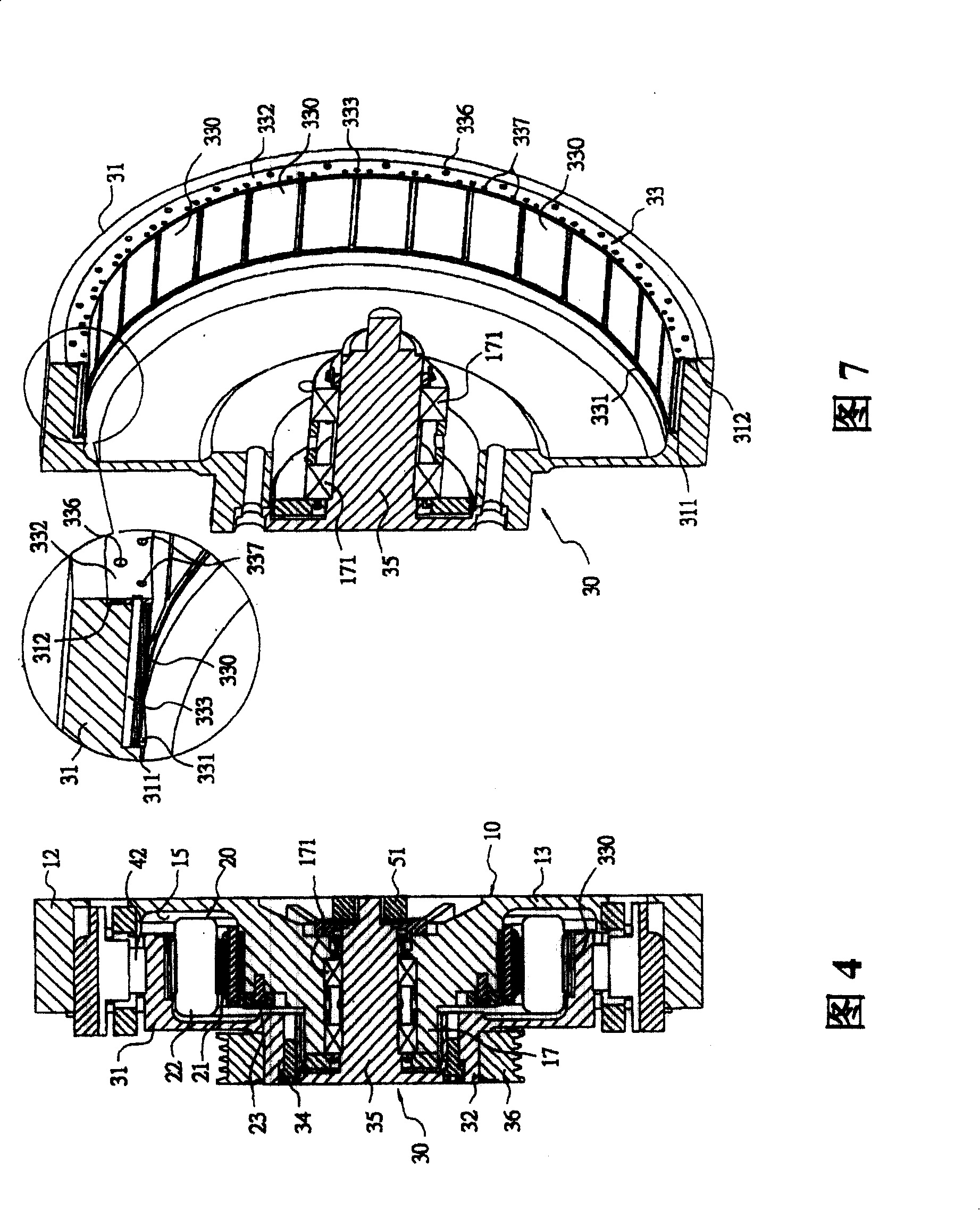
[0076] First of all, please refer to Fig. 1 and compare Fig. 2 to Fig. 4, the external rotation permanent magnet motor 1 of the present invention mainly includes: a base body 10, the outer frame of which includes two side structures 11 in the direction of the long axis, and two short The side structure 12 in the axial direction, the base 10 has a bottom 13 on one side, and the other side is open, and contains a pair of semi-annular reinforcing ribs 14 in the direction of the long axis to form a storage chamber 15, and two pairs of reinforcement ribs in the direction of the long axis. The reinforcing ribs 16 are respectively connected between the two ends of the two halves of the annular reinforcing ribs 14 and the side structure 12 in the direction of the minor axis and become one; the center of the base 10 extends from the bottom 13 toward the storage chamber 15 with a hollow bearing Cover 17, and is provided with a plurality of bearings 171 in its central shaft hole.

[0077...


PUM


Abstract

The motor comprises a basal body and a rotor. An external frame of the basal body comprises edge structures along direction of two long axes and two short axes. A stator in use for excitation is accommodated inside the basal body. Including a brake drum with multiple pieces of permanent magnet units installed inside, the rotor sheathed outside the stator is in use for generating torque of magnetic force. An installation part formed in inner side of the brake drum is in use for fixing a positioning frame. The said positioning frame composed of two annular inner and outer pressure plates and peripherals forms multiple accommodation spaces. Permanent magnet units are embedded inside the said accommodation spaces. The positioning frame fixes multiple pieces of permanent magnet units on inner side of the brake drum in order to improve reliability of stuck magnet units and enhance intensity. Four pieces of edge structures can be as installation faces to adapt each conditions of installation.

Description

technical field [0001] The invention relates to a rotor externally rotating permanent magnet motor, in particular to a positioning circular frame that can arrange and fix a plurality of permanent magnets at equal intervals on the inner wall of the brake drum of the rotor to ensure the interval between the permanent magnets Permanent magnet motor with correctness and stability of attachment and positioning. Background technique [0002] The rotational power of the motor is the interaction of the magnetic field generated by the current between the rotor and the stator, and the electrical energy is converted into rotational mechanical energy. Due to the continuous development of new high-permeability permanent magnet materials, the volume and weight of permanent magnets are smaller and the magnetism is stronger. Therefore, the permanent magnet motor made of this high-permeability electromagnet is different from the traditional winding motor Compared with the same torque of the...

Claims


Application Information

Patent Timeline
Patent Type & Authority Patents(China)
IPC IPC(8): H02K21/14H02K1/27
Inventor 蔡东育许世昌吴尊耀郭庆修颜睿廷陈建仁
Owner YUNG TAY ENG
Why Eureka
Try Eureka