
Method for placing ground wire in producing cable and device thereof

A grounding wire and cable technology, used in insulated cables, cable/conductor manufacturing, cables, etc., can solve the problems of small bumps, cable sheath hook-shaped protrusions, grounding wire breakage, etc., to eliminate hook-shaped protrusions or grounding Effect of wire breakage, enhanced flexibility, and improved electrical performance

Inactive Publication Date: 2008-07-02
上海汉欣电线电缆有限公司
View PDF3 Cites 0 Cited by
  • Summary
  • Abstract
  • Description
  • Claims
  • Application Information

AI Technical Summary

Problems solved by technology

At present, in the production process of this type of cable, the grounding wire and the core wire enter in parallel, re-braid or wrap the shielding layer longitudinally. When passing the traction wheel and the guide wheel, the grounding wire will protrude, especially when the sheath layer is squeezed There will be small bumps on the surface; in this way, when the cable is bent during construction, the cable sheath will have a hook-like protrusion or the grounding wire will break, which will affect the use of the cable.

Method used

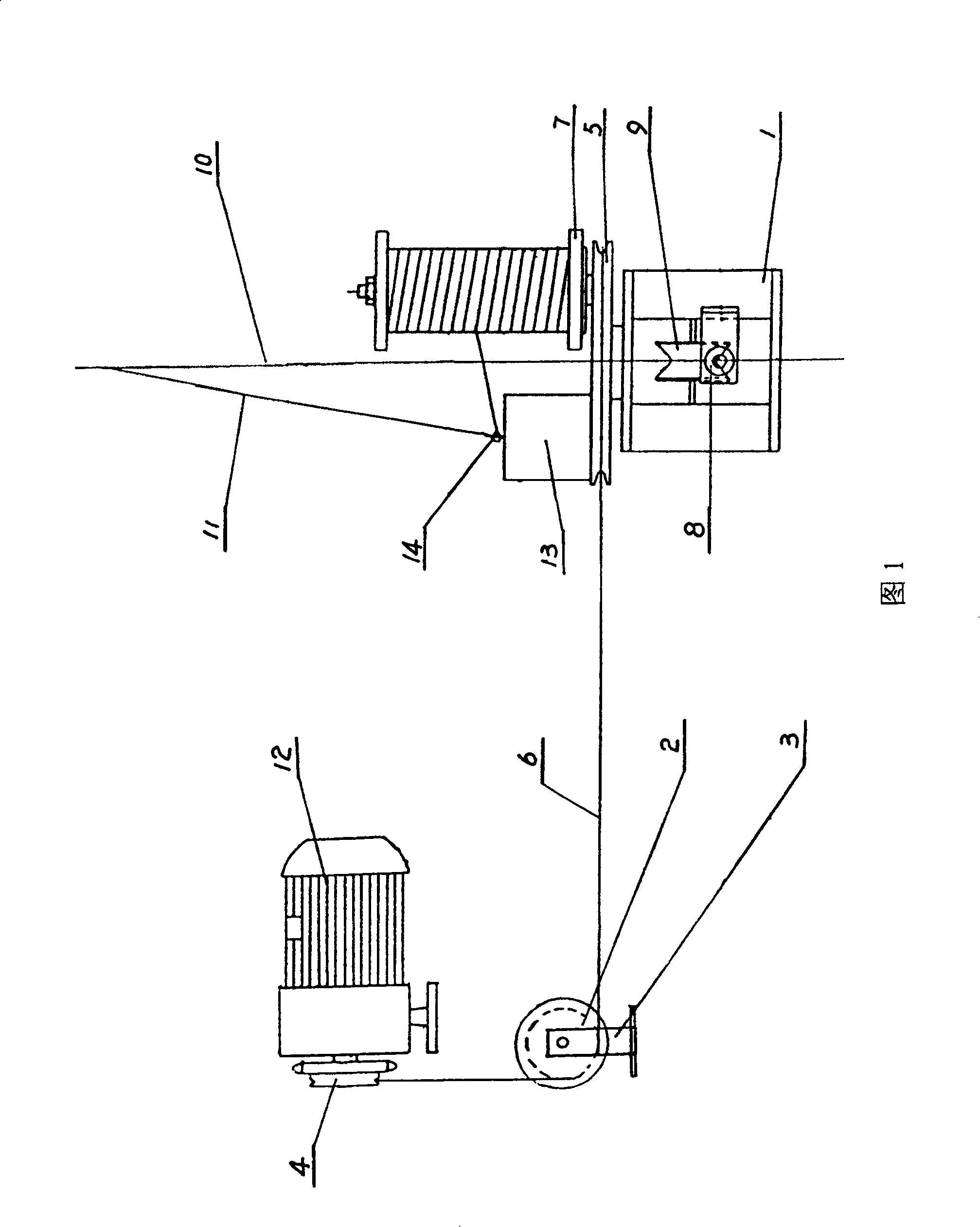
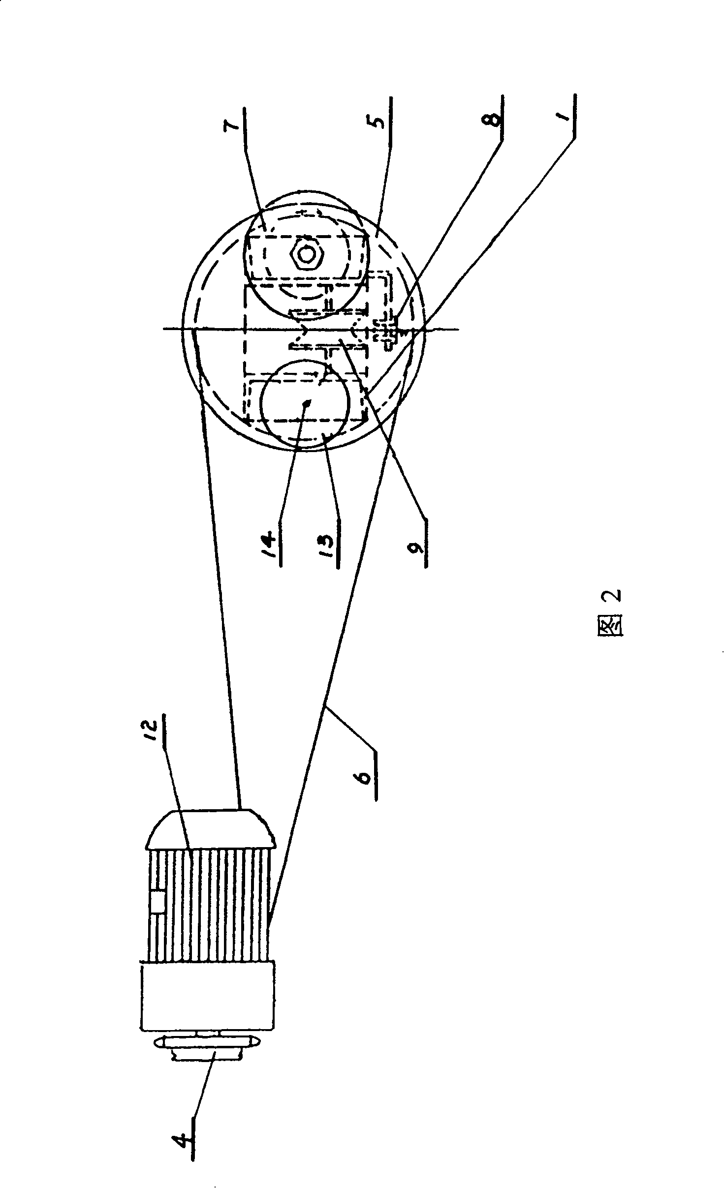
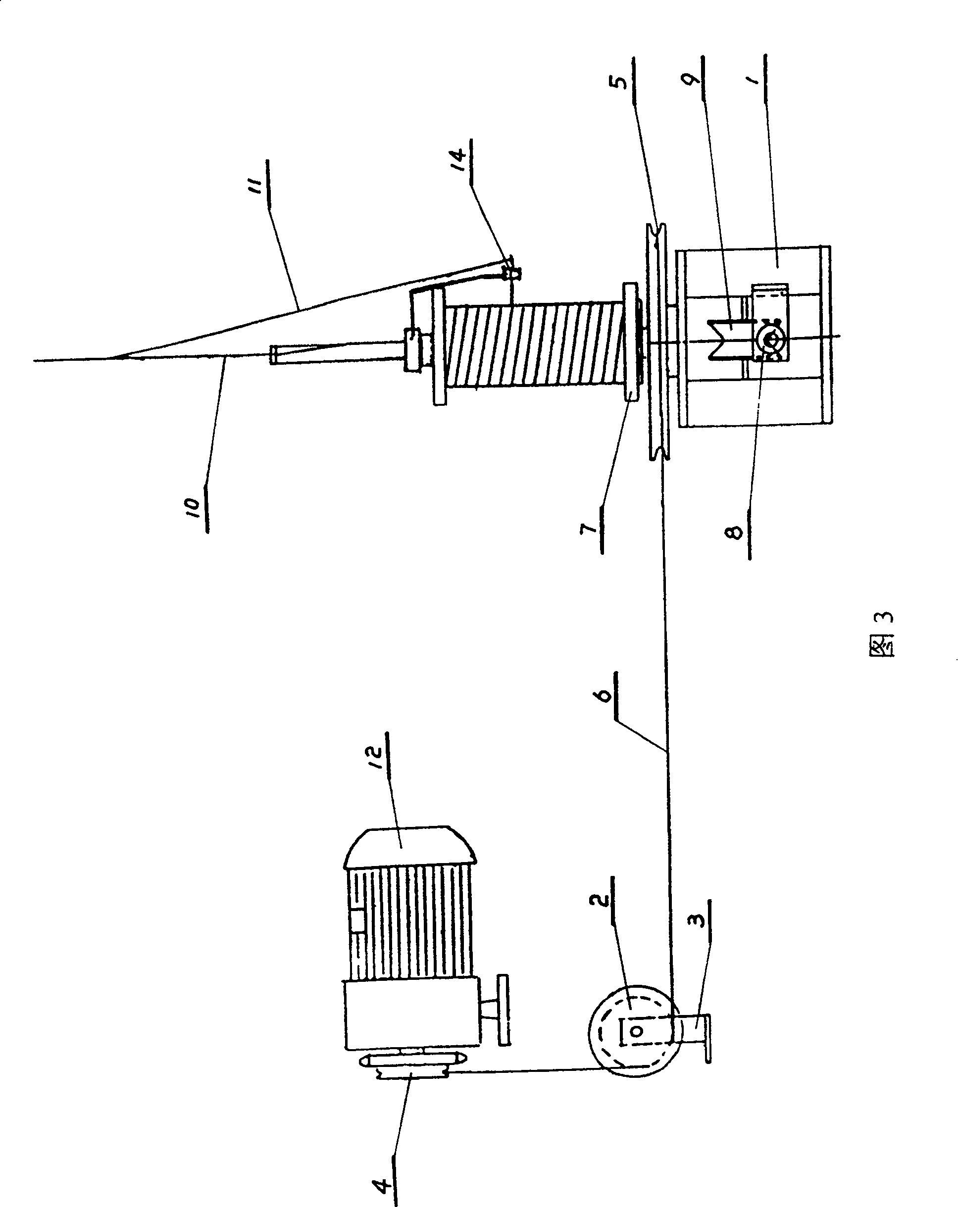

Image

  • Method for placing ground wire in producing cable and device thereof
  • Method for placing ground wire in producing cable and device thereof
  • Method for placing ground wire in producing cable and device thereof

Examples


Embodiment 1

[0012] Referring to Fig. 1, 2, the present invention comprises support 1, steering wheel 2, steering wheel bracket 3, driving and driven wheels 4,5, belt 6, and driving wheel 4 connects the take-up motor 12 in the original equipment, and steering wheel 2 is provided with On the steering wheel bracket 3, the driven wheel 5 is located on the support 1, and the belt 6 connects the driving wheel 4, the steering wheel 2 and the driven wheel 5; Wire passing die 8 and core wire guide wheel 9 are arranged under the wheel 5; in the cable production process, when the shielding layer needs to be braided or wrapped, the braiding machine is started, and the wire take-up motor 12 runs simultaneously when the braiding disc is running. The belt 6 in the present invention drives the driving and passive wheels 4, 5 to rotate, and the grounding wire reel 7 rotates at the same time, so that the grounding wire 11 on it is wound around the wire that enters through the wire passing mold 8 and the cor...

Embodiment 2

[0014] Referring to Fig. 3, the present invention comprises support 1, steering wheel 2, steering wheel bracket 3, driving and passive wheels 4,5, belt 6, and driving wheel 4 connects the take-up motor 12 in the original equipment, and steering wheel 2 is located at the steering wheel On the wheel bracket 3, the driven wheel 5 is located on the support 1, and the belt 6 connects the driving wheel 4, the steering wheel 2 and the driven wheel 5; The bottom is provided with a wire passing mold 8 and a core wire guide wheel 9; in the cable production process, when it is necessary to weave or wrap the shielding layer, start the weaving machine, and when the weaving disc is running, the take-up motor 12 is running at the same time. The belt 6 in the invention drives the driving and passive wheels 4 and 5 to rotate, and the ground wire reel 7 rotates at the same time, so that the ground wire 11 on it is wound around the core wire that enters through the wire passing mold 8 and the cor...


PUM


Abstract

This invention discloses earth wire placement method and device when generating cable. The method is that the wire is wound on the core, and then shielding layer is weaved or coated. The device includes support frame, directive wheel, directive wheel bracket, driving and driven wheel and belt. The driving wheel is connected to the motor, the directive wheel is set on the bracket, the driven wheel is set on the support, the belt is connected to the driving wheel, directive wheel and driven wheel, earth wire coil is set on the driven wheel axis, and wire module core idler pulley are set below the driven wheel. The earth wire parallel with the core is volute enwound on the core, so the wire reliability is enhanced, hooked heave or earth wire fracture during execution are lightened, and the cable electrical specification is improved.

Description

technical field [0001] The invention relates to cable production technology, in particular to a device for placing grounding wires during cable production. Background technique [0002] In the manufacture of data cables, symmetrical cables and other cables that require a shielding layer, in the production process of using multi-strand metal wire braiding or aluminum foil as the shielding layer, a grounding wire must be added to achieve shielding grounding and improve electrical performance. At present, in the production process of this type of cable, the grounding wire and the core wire enter in parallel, re-braid or wrap the shielding layer longitudinally. When passing the traction wheel and the guide wheel, the grounding wire will protrude, especially when the sheath layer is squeezed There will be small bumps on the surface; in this way, when the cable is bent during construction, the cable sheath will have a hook-like protrusion or the grounding wire will break, which wi...

Claims


Application Information

Patent Timeline
Patent Type & Authority Patents(China)
IPC IPC(8): H01B13/00H01B7/00
Inventor 汪家克何胜荣
Owner 上海汉欣电线电缆有限公司
Learn More