Heat compensated oil collection tank

An oil collecting tank and thermal compensation technology, applied in fractionation and other directions, can solve problems such as large thermal deformation, affecting normal operation, and oil collecting tank damage, and achieve the effect of reducing residence time, ensuring normal operation, and preventing coking.

Active Publication Date: 2008-07-09
TIANJIN UNIV +1
View PDF4 Cites 0 Cited by
  • Summary
  • Abstract
  • Description
  • Claims
  • Application Information

AI Technical Summary

Problems solved by technology

[0004] However, after the application in various large-scale towers in recent years, it is found that although the grooved-disk oil collection tank can obviously improve the contradiction between liquid collection and gas distribution, the traditional grooved-disk oil collection tank has a higher temperature In some cases, due to the large thermal deformation, it often affects normal operation and even causes damage to the oil collection tank. Therefore, the traditional grooved plate oil collection tank cannot solve the problem of thermal expansion at high temperatures

Method used


Image

  • Heat compensated oil collection tank
  • Heat compensated oil collection tank
  • Heat compensated oil collection tank

Examples


Embodiment 1

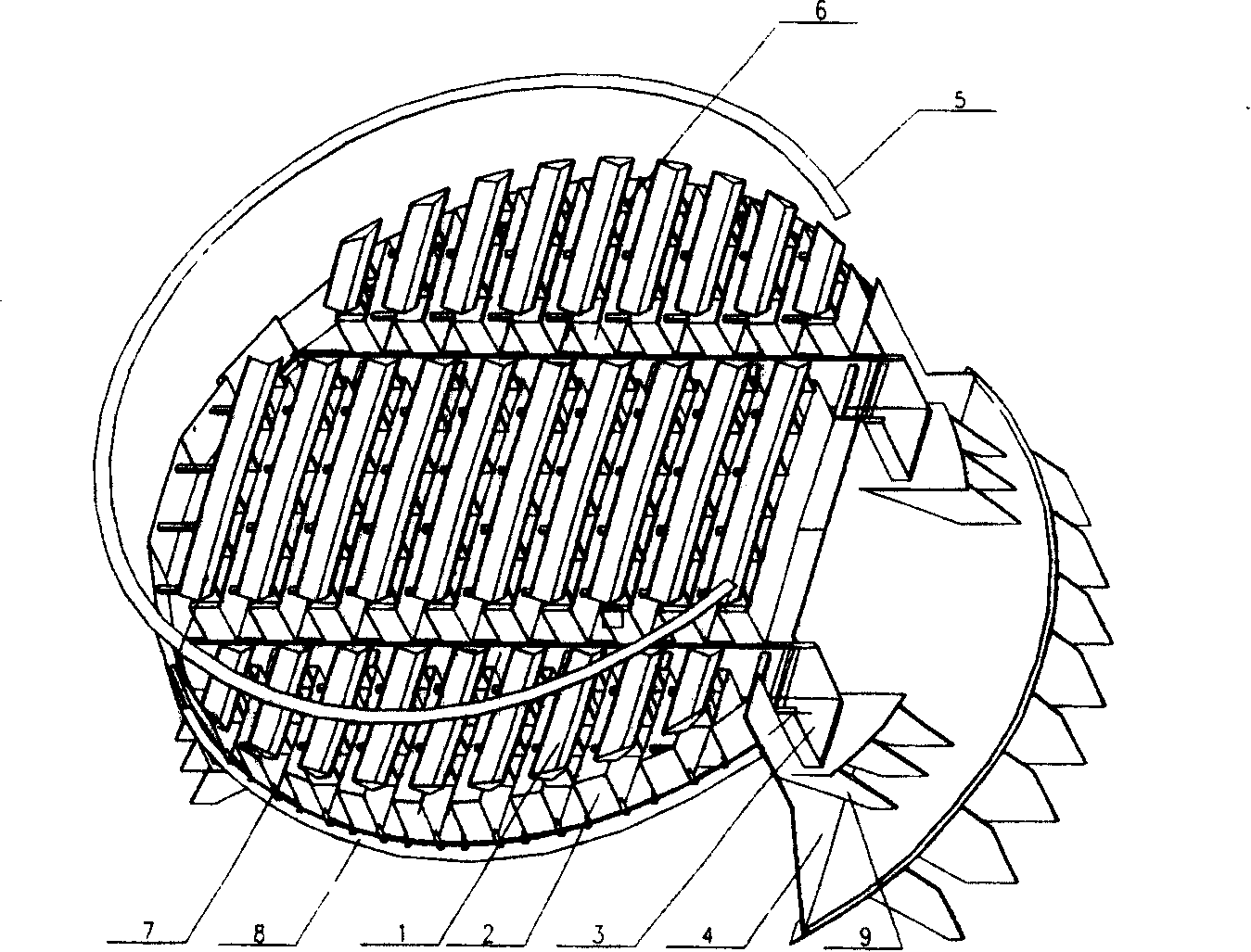
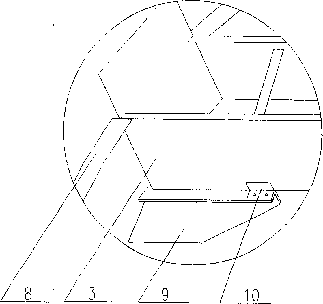
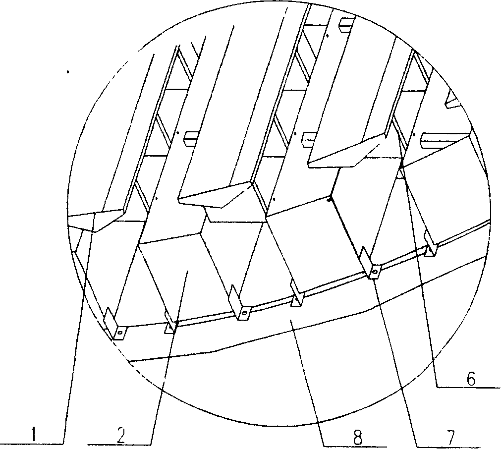
[0025] Such as figure 1 As shown, the heat-compensated oil collection tank includes a liquid collection cap 1, a liquid collection tank 2, a liquid collection channel 3, an extraction bucket 4, a liquid shielding ring 5, a support rib 6, a liquid collection tank limiter 7, a tower ring 8, Components such as the support 9, the liquid collecting channel limiter 10 and the limit expansion ring 11 (wherein the tower ring 8 and the supporting seat 9 are common parts in the tower, and will not be elaborated in the present invention.), the liquid collecting channel 3 The fixed end of the sump is fixed on the extraction bucket 4 or the support 9, the free end is lapped on the support 9 and the lateral position is limited by two sump stoppers 10, and the fixed end of the sump 2 is fixed on the sump 3, the free end is lapped on the tower ring 8 and its lateral position is limited by two liquid sump stoppers 7, the liquid collecting cap 1 is fixed between the liquid sump 2 through the su...

Embodiment 2

[0031] The difference from Example 1 is that when there are two or more sumps 3, the fixed end of the sump 2 between the sump 3 and the support 9 is fixed on the side plate of the sump 3, and the free end It is sealed by a blocking plate and rests on the tower ring 8, and the lateral position is limited by the liquid sump limiter 7, and its thermal deformation can be compensated by the free expansion and contraction in the longitudinal direction. Both ends of the sump 2 located between the two sump channels 3 are fixed on the side plates of the sump channels 3 , and its thermal deformation can be compensated by the deformation of the side plates of the sump channels 3 .

Embodiment 3

[0033] The difference from Example 1 is that when there are two or more collecting channels 3, both ends of the collecting channel 2 located between the two collecting channels 3 are open, so that the liquid flows to the collecting channels on both sides respectively. within 3.


PUM


Abstract

The invention relates to a thermal compensation oil tank. It comprises holding cap, holding tank, holding ditch and drawing bucket; one end of holding ditch is fixed jointed, and the other end is freely jointed, the two sides of holding ditch are equipped with stop in cross direction; one end of holding tank ais fixed jointed and the other end is freely jointed, the two sides of holding tank are equipped with stop in cross direction; the holding cap is installed between holding tank. The thermal compensation oil tank possesses good gas distribution and liquid collection property, reduces liquid retention time, avoids coking, and expands freely under high temperature and gurantee normal operation of tower under high temperature.

Description

technical field [0001] The invention relates to an internal part of a chemical tower, in particular to a grooved plate heat compensation type oil collecting tank used for liquid collection and gas distribution in the chemical tower. technical background [0002] In the departments of oil refining, petrochemical, fine chemical, food, medicine and environmental protection, towers are important unit equipment with a large volume and wide range, and their investment generally accounts for about 20% of the total investment, and some even as high as 50%. Columns are widely used in unit operations such as distillation, absorption, extraction, washing, and heat transfer. Therefore, the research on towers has always been an important issue that scholars at home and abroad have generally paid attention to. [0003] With the development of tower equipment, the technology of tower internals has also been continuously developed and improved. Various new tower internal structures have em...

Claims


Application Information

Patent Timeline
Patent Type & Authority Patents(China)
IPC IPC(8): B01D3/32
Inventor 姜斌李鑫钢许长春袁毅夫王自依
Owner TIANJIN UNIV
Why Eureka
Try Eureka