Driving mechanism with eccentric round cam groove

A technology of eccentric cam and transmission mechanism, which is applied in transmission devices, mechanical equipment, belts/chains/gears, etc. It can solve problems such as energy consumption, complex structure, and large swing friction, and achieve simple structure, reliable transmission, and stable high-speed operation Effect

Inactive Publication Date: 2008-07-16
王良知
View PDF8 Cites 1 Cited by
  • Summary
  • Abstract
  • Description
  • Claims
  • Application Information

AI Technical Summary

Problems solved by technology

However, the crank mechanism is not suitable for linear reciprocating motion with a large distance. The eccentric shaft mechanism is actually a rocker arm rotation mechanism with a relatively complicated structure and a large volume.
Especially in the reciprocating stroke, the friction of the swing is large, and it is impossible to achieve a balance, which consumes a lot of energy

Method used


Image

  • Driving mechanism with eccentric round cam groove
  • Driving mechanism with eccentric round cam groove
  • Driving mechanism with eccentric round cam groove

Examples


Embodiment 1

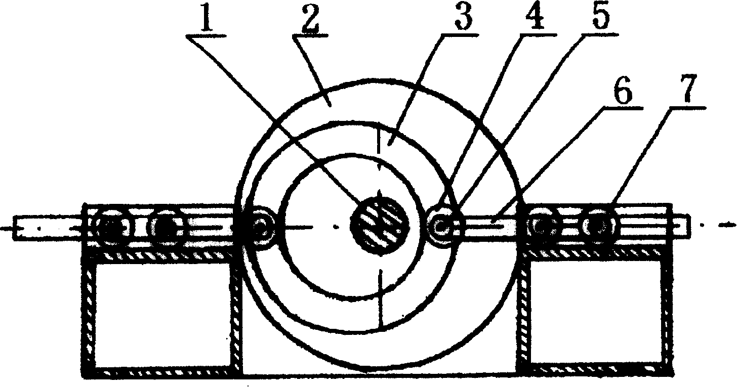
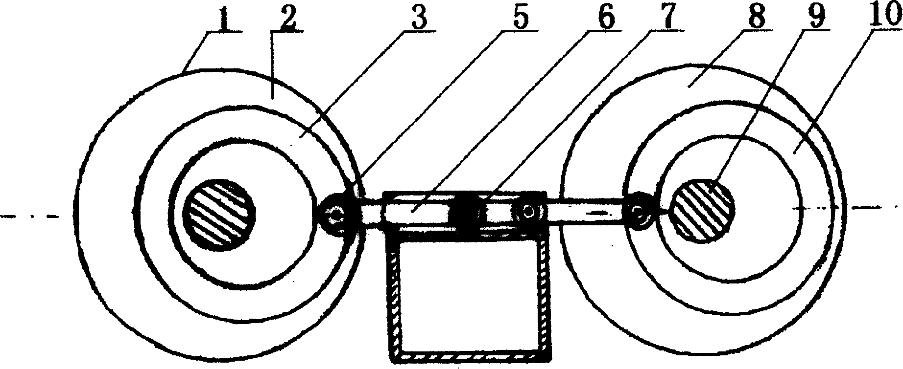
[0011] Embodiment 1, by figure 1 It can be seen that the eccentric cam body 2 of the present invention can adopt a circular eccentric cam body, so that its manufacture is more convenient. The rotating shaft 1 passes through the center of the circular eccentric cam body 2, even if the rotating shaft 1 coincides with the axis line of the eccentric cam body 2. The circular eccentric cam body 2 is provided with a circular groove 3 deviated from the axis line of the rotary shaft 1 around the rotating shaft 1, which can be on one side of the circular eccentric cam body 2 or on both sides of the circular eccentric cam body 2. Set round slot 3. Because the transmission rod 6 is set in the guide groove that can only reciprocate longitudinally, when the power device drives the circular eccentric cam disc body 2 to rotate through the rotating shaft 1, so that the circular groove 3 deviated from the axis line of the rotating shaft 1 performs an eccentric circular motion, One end is driv...

Embodiment 2

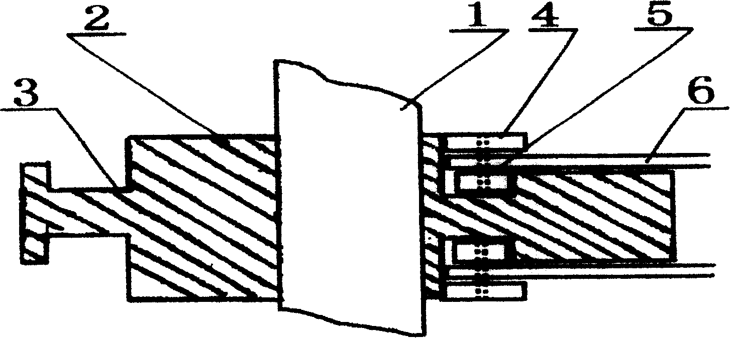
[0013] Embodiment 2, in order to make the movement smoother, the eccentric cam body 2 adopts a circular eccentric cam body, and the thickness inside the circular groove 3 is greater than the thickness outside the circular groove 3, and the connecting rod 6 is set in the circular groove 3 Roller 5 is sleeved on the axle. In order to make the transmission more reliable, a roller 5 is set at the bottom of the circular groove 3 at the inner end of the connecting shaft of the transmission rod 6. The roller 5 is in contact with the outer wall of the circular groove 3, and a large roller 4 is installed on the outside of the connecting shaft. It is in contact with the inner wall of the circular groove 3, so that the transmission rod 6 and the circular groove 3 are tightly fitted and in smooth contact.

[0014] It is also possible to set rollers 7 on the transmission rod 6, or to set different rollers 7 with different inner diameters on both sides, and the transmission rod 6 is sleeved...

Embodiment 3

[0015] Embodiment 3, in order to make the movement of the whole mechanism more stable without vibration, the gravity balance can be realized by making the eccentric cam disc body 2 provided with the circular groove 3 take the axis line of the rotating shaft 1 as the axis line, so that the gravity is balanced with the axis line of the rotating shaft 1 is a balanced distribution of the center line, so that when the eccentric cam body 2 rotates around the rotating shaft 1, the movement of the mechanism is very stable. All the other are with embodiment 1 or 2.


PUM


Abstract

A slotted eccentrical circular cam type drive mechanism features that an eccentrical wheel installed to central axle has an eccentrical ring slot on its circumferential surface, the longitudinally reciprocating drive rods are respectively installed in their guide tubes, and the sleeved end of said drive rod is arranged vertically in said ring slot on eccentrical cam. Its advantages are simple structure, and high stability and reliability.

Description

technical field [0001] The invention relates to a mechanical transmission mechanism, in particular to a mechanical transmission mechanism for mutual conversion between circular motion and linear reciprocating motion. Background technique [0002] At present, the transmission mechanisms for mutual conversion between circular motion and linear reciprocating motion mainly include crank mechanism and eccentric shaft mechanism. However, the crank mechanism is not suitable for rectilinear reciprocating motion with a large distance. The eccentric shaft mechanism is actually a rocker arm rotation mechanism with a relatively complicated structure and a large volume. In particular, the swing friction in the reciprocating stroke is large, and it is impossible to reach a balance, which consumes a lot of energy. Contents of the invention [0003] The purpose of the present invention is to provide a simple in structure, economical and practical eccentric circular cam groove transmissio...

Claims


Application Information

Patent Timeline
Patent Type & Authority Patents(China)
IPC IPC(8): F16H25/08
Inventor 王良知
Owner 王良知
Why Eureka
Try Eureka