Image forming apparatus having a plurality of laser scanner units
A laser scanning and laser technology, applied in optical components, optics, electrical recording technology using charge patterns, etc., can solve the problem of losing the cost advantage of double cassettes
- Summary
- Abstract
- Description
- Claims
- Application Information
AI Technical Summary
Problems solved by technology
Method used
Image
Examples
no. 1 Embodiment approach
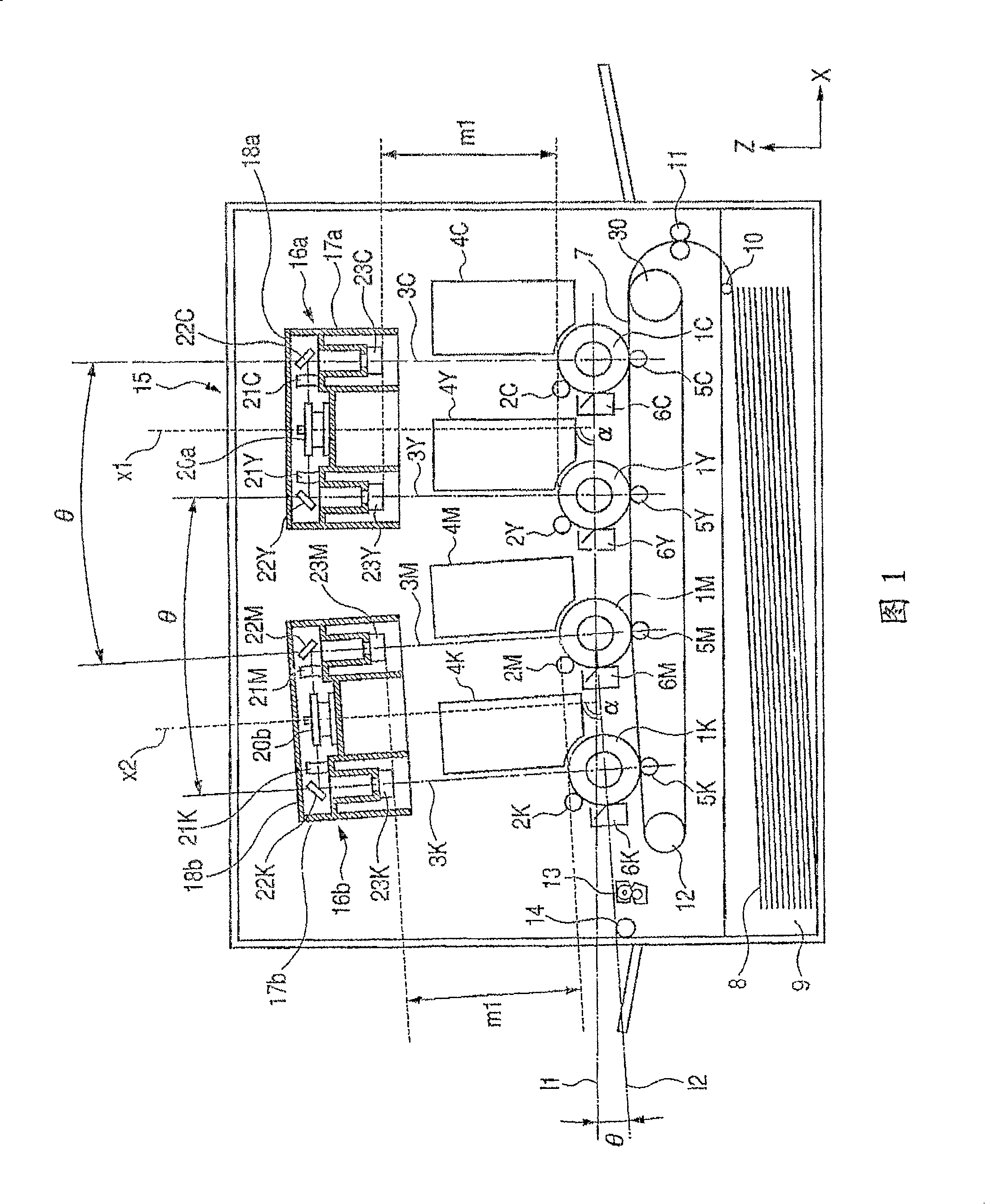
[0049] The first embodiment of the present invention will be described using the drawings. FIG. 1 is an explanatory diagram of an image forming apparatus according to a first embodiment. In the description, the entire image forming apparatus will be described first, and then the structure of the scanning optical device (laser scanning unit) will be described.
[0050] (image forming device)
[0051] FIG. 1 is a diagram showing an image forming apparatus 15 according to an embodiment of the present invention. The image forming apparatus 15 is capable of superimposing toner images of four colors (cyan C, yellow Y, magenta M, and black K) to form a color image, and has four image forming stations. Each image forming station has a first image carrier (photosensitive drum 1C), a second image carrier (photosensitive drum 1Y), a third image carrier (photosensitive drum 1M), and a fourth image carrier (photosensitive drum 1K).
[0052]In addition, the image forming apparatus 15 has...
no. 2 Embodiment approach
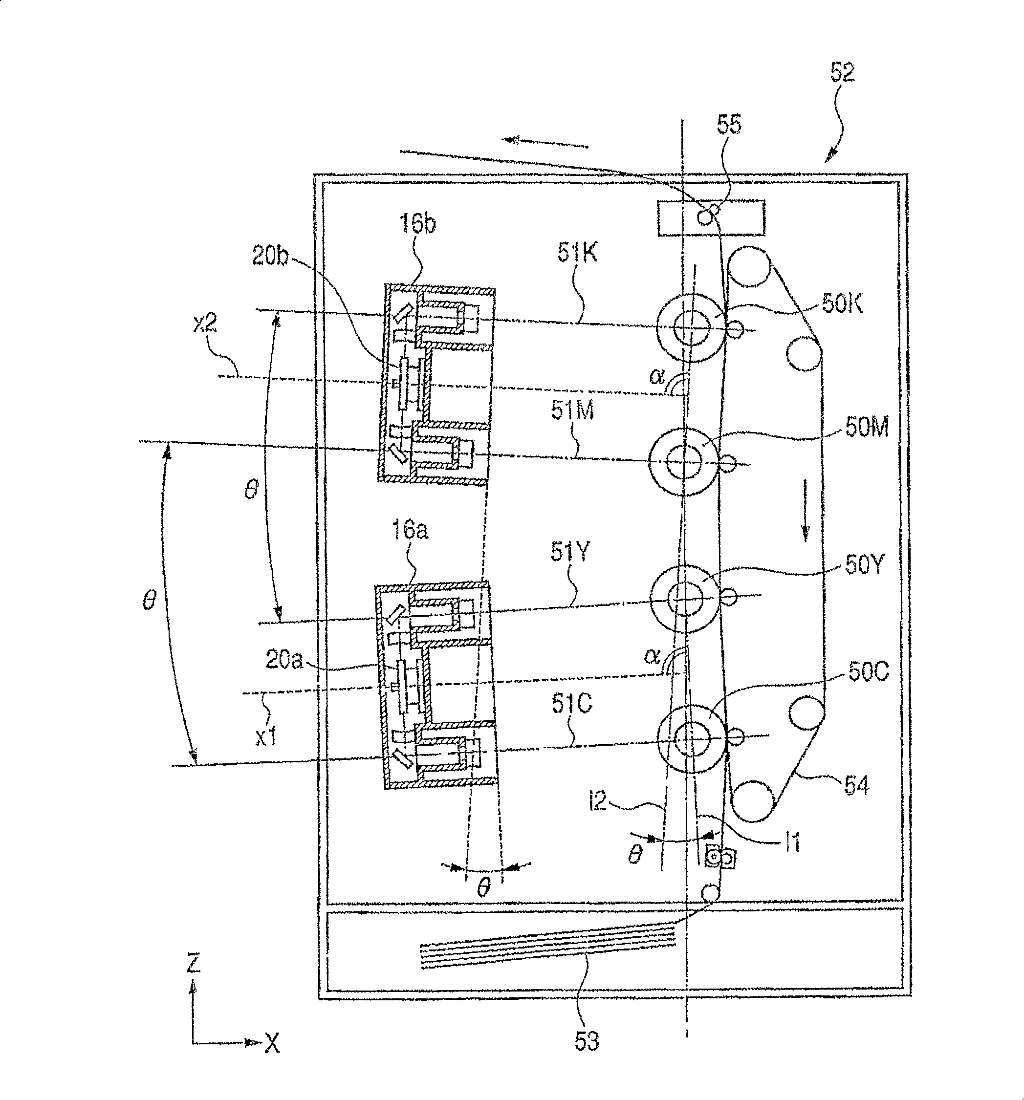
[0094] use image 3 A second embodiment of the present invention will be described. image 3 It is an explanatory diagram of the image forming apparatus of the second embodiment. In the description, the description of the same configuration as above is omitted.
[0095] (image forming device)
[0096] Such as image 3 As shown, the image forming apparatus 52 of this embodiment includes the above-mentioned first scanning optical device 16a and second scanning optical device 16b.
[0097]Light beams 51C, 51Y, 51M, and 51K emitted from scanning optical devices 16a, 16b form latent images on the surfaces of photosensitive drums 50C, 50Y, 50M, and 50K similarly to the above-described embodiments. Among the four photosensitive drums, the black and cyan photosensitive drums 50K, 50C at both ends in the vertical direction (Z direction in the figure) of the image forming device 52 are sent to the transfer material conveyor belt with respect to the magenta and yellow photosensitive ...
no. 3 Embodiment approach
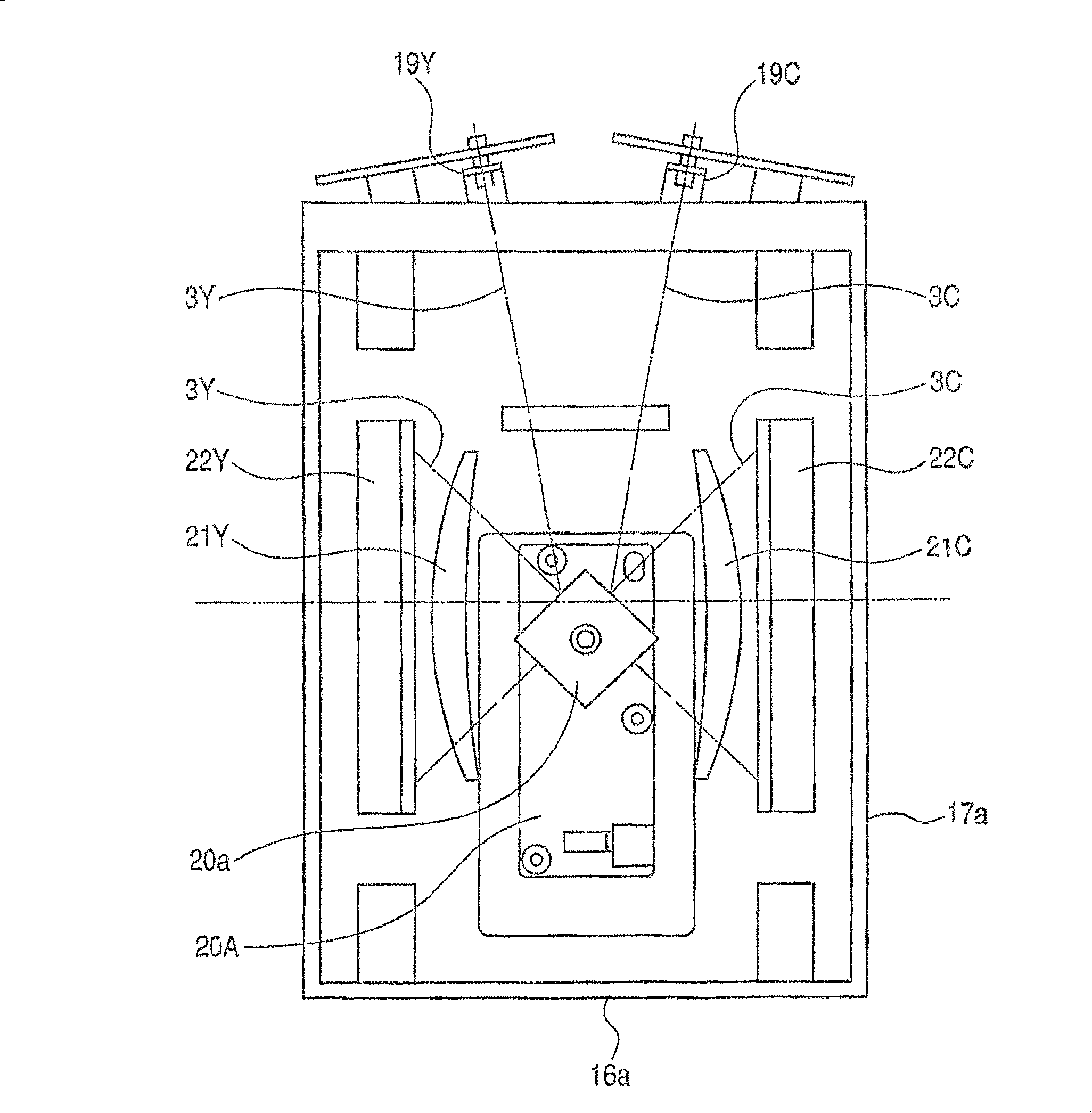
[0105] Figure 13 and Figure 14 The third embodiment is shown. In the first and second embodiments described above, the optical path shape of the third laser beam is approximately the same as that of the first laser beam, and the optical path shape of the fourth laser beam is approximately the same as that of the second laser beam. On the other hand, in this embodiment, the optical path shape of the first laser beam is substantially the same as that of the fourth laser beam, and the optical path shape of the second laser beam is substantially the same as that of the third laser beam. At this time, if Figure 14 As shown, the two light sources 19C and 19Y mounted on the first laser scanning unit 16a are arranged on one side (the front side in this embodiment) of the image forming apparatus, and the two light sources 19C and 19Y mounted on the second laser scanning unit 16b The individual light sources 19M and 19K are arranged on the other side (rear side in this embodiment). ...
PUM
 Abstract
Description
Claims
Application Information
 - R&D
- Intellectual Property
- Life Sciences
- Materials
- Tech Scout
- Unparalleled Data Quality
- Higher Quality Content
- 60% Fewer Hallucinations
Browse by: Latest US Patents, China's latest patents, Technical Efficacy Thesaurus, Application Domain, Technology Topic, Popular Technical Reports.
© 2025 PatSnap. All rights reserved.Legal|Privacy policy|Modern Slavery Act Transparency Statement|Sitemap|About US| Contact US: help@patsnap.com


