
Electro-optical device, driving circuit thereof, and electronic apparatus

A technology for driving circuits and electro-optical devices, which is applied to instruments, static indicators, etc., and can solve problems such as display quality degradation and image retention

Inactive Publication Date: 2008-07-23
SEIKO EPSON CORP
View PDF6 Cites 0 Cited by
  • Summary
  • Abstract
  • Description
  • Claims
  • Application Information

AI Technical Summary

Problems solved by technology

Therefore, despite the AC drive, the DC component is applied to the liquid crystal capacitor, causing image retention, and flickering occurs during positive polarity writing and negative polarity writing, resulting in a significant decrease in display quality

Method used


Image

  • Electro-optical device, driving circuit thereof, and electronic apparatus
  • Electro-optical device, driving circuit thereof, and electronic apparatus
  • Electro-optical device, driving circuit thereof, and electronic apparatus

Examples


Embodiment Construction

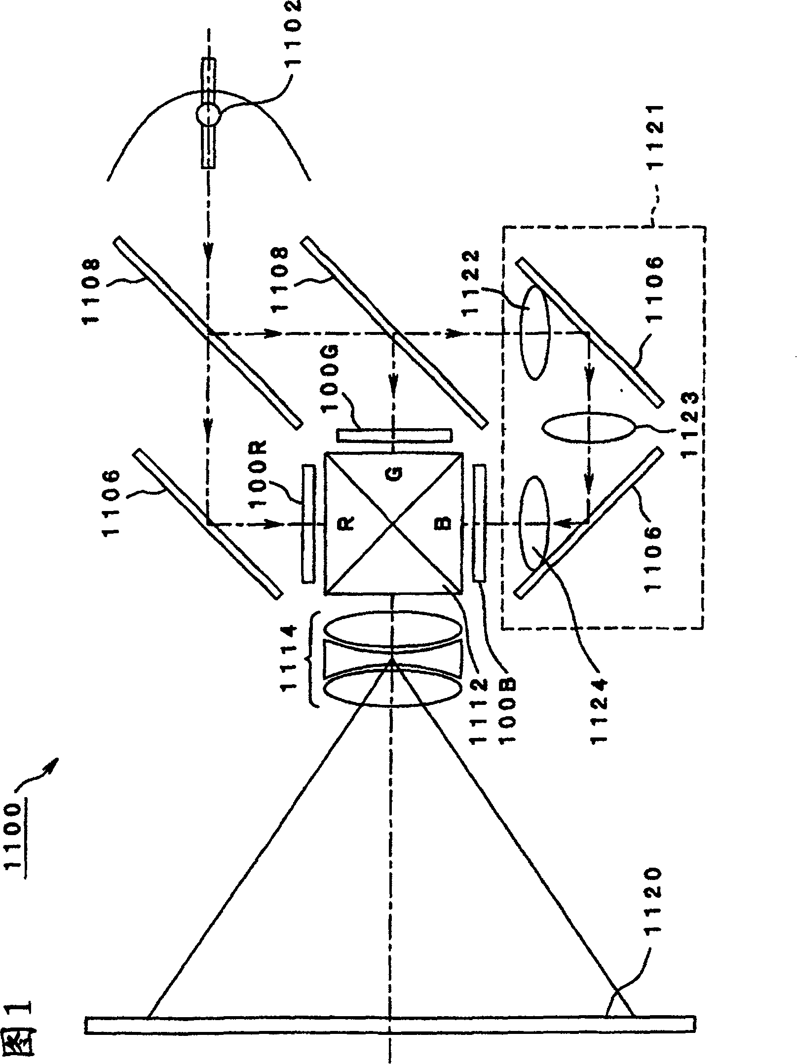
[0042] Hereinafter, embodiments of the present invention will be described in detail with reference to the drawings. FIG. 1 is an explanatory view showing an electro-optical device according to one embodiment of the present invention. This embodiment is applied to a projector that synthesizes the transmitted images of the liquid crystal panel and performs enlarged projection.

[0043] Example.

[0044] First, the configuration of the optical system of the projector will be schematically described with reference to FIG. 1 .

[0045] In FIG. 1 , a lamp unit 1102 including a white light source such as a halogen lamp is provided inside a projector 1100 . Projected light emitted from the lamp unit 1102 is separated into three primary colors of R (red), G (green), and B (blue) by three reflectors 1106 and two dichroic mirrors 1108 arranged inside, and guided to on the liquid crystal panels 100R, 100G, and 100B corresponding to the primary colors.

[0046] Among them, R, G, and B...


PUM


Abstract

The objective is to control an optimum LC common voltage within a plane to be equivalently uniform and to prevent the occurrence of a burn-in phenomenon and flicker. A driving circuit includes a storing means 322 and a correcting means 326. The storing means stores a correction value corresponding to a pixel position of a display section 100a in which pixels are formed so as to correspond to intersections of a plurality of source lines and a plurality of scanning lines arranged in a matrix and which performs pixel display by allowing an image signal supplied to the source line to be applied to a pixel electrode of each pixel via a switching element when the switching element disposed in the pixel is turned on by a scanning signal supplied to the scanning line. The correcting means receives an image signal for polarity reverse driving and independently, adds the correction value from the storing means to image signals having a positive polarity and having a negative polarity, and supplies the signals to the display section.

Description

technical field [0001] The present invention relates to an electro-optic device, a drive circuit thereof, and an electronic device for appropriately reducing so-called flicker over the entire display area. Background technique [0002] Electro-optical devices, for example, liquid crystal display devices using liquid crystals as electro-optic substances, have been widely used as display devices replacing cathode ray tubes (CRTs) in display units of various information processing devices, liquid crystal televisions, and the like. [0003] Such a liquid crystal display device, for example, is composed of pixel electrodes arranged in a matrix, an element substrate provided with switching elements such as TFTs (Thin Film Transistor: thin film transistors) connected to the pixel electrodes, and a pair of pixels facing the pixel electrodes is formed. It consists of a counter substrate with electrodes and a liquid crystal as an electro-optic substance filled between the two substrat...

Claims


Application Information

Patent Timeline
Patent Type & Authority Patents(China)
IPC IPC(8): G09G3/36G09G3/20G02F1/133
CPCG09G2320/0247G09G2320/0214G09G2320/0233G09G2320/0219G09G2320/0285G09G3/3614G09G3/3688G09G2320/0223
Inventor 青木透
Owner SEIKO EPSON CORP
Features
  • Generate Ideas
  • Intellectual Property
  • Life Sciences
  • Materials
  • Tech Scout
  • Unparalleled Data Quality
  • Higher Quality Content
  • 60% Fewer Hallucinations
Learn More