Heating power pump

A heat pump and pump body technology, applied in the field of energy exchange devices, can solve the problems of low energy transfer and conversion rate, high cost, high energy consumption, etc., achieve energy saving effects and improved heat transfer effects, small heat loss, and high capacity Improved effect

Inactive Publication Date: 2008-08-13
牟省先
View PDF5 Cites 7 Cited by
  • Summary
  • Abstract
  • Description
  • Claims
  • Application Information

AI Technical Summary

Problems solved by technology

Although they can transfer and convert energy, they all have the disadvantages of high energy consumption, high cost, complex structure, energy exchange and low transfer rate.
Moreover, for some energy conversion and transfer devices, such as heat pipes, the medium cannot use chemically stable, low-cost, and non-polluting water, but only chemically unstable medium (such as Freon). Once the medium leaks, it will cause environmental pollution. Pollution
I applied for a utility model patent named vortex diversion pump in 1992. Its patent publication number is CN2112025U. In fact, it is also a heat pump, although it solves the problem of heat carrier medium from disorder to order. , however, due to the limitation of its heat source device outside the pump body and only axial flow guides, the energy transfer and conversion rate are low

Method used


Image

  • Heating power pump
  • Heating power pump

Examples


Embodiment

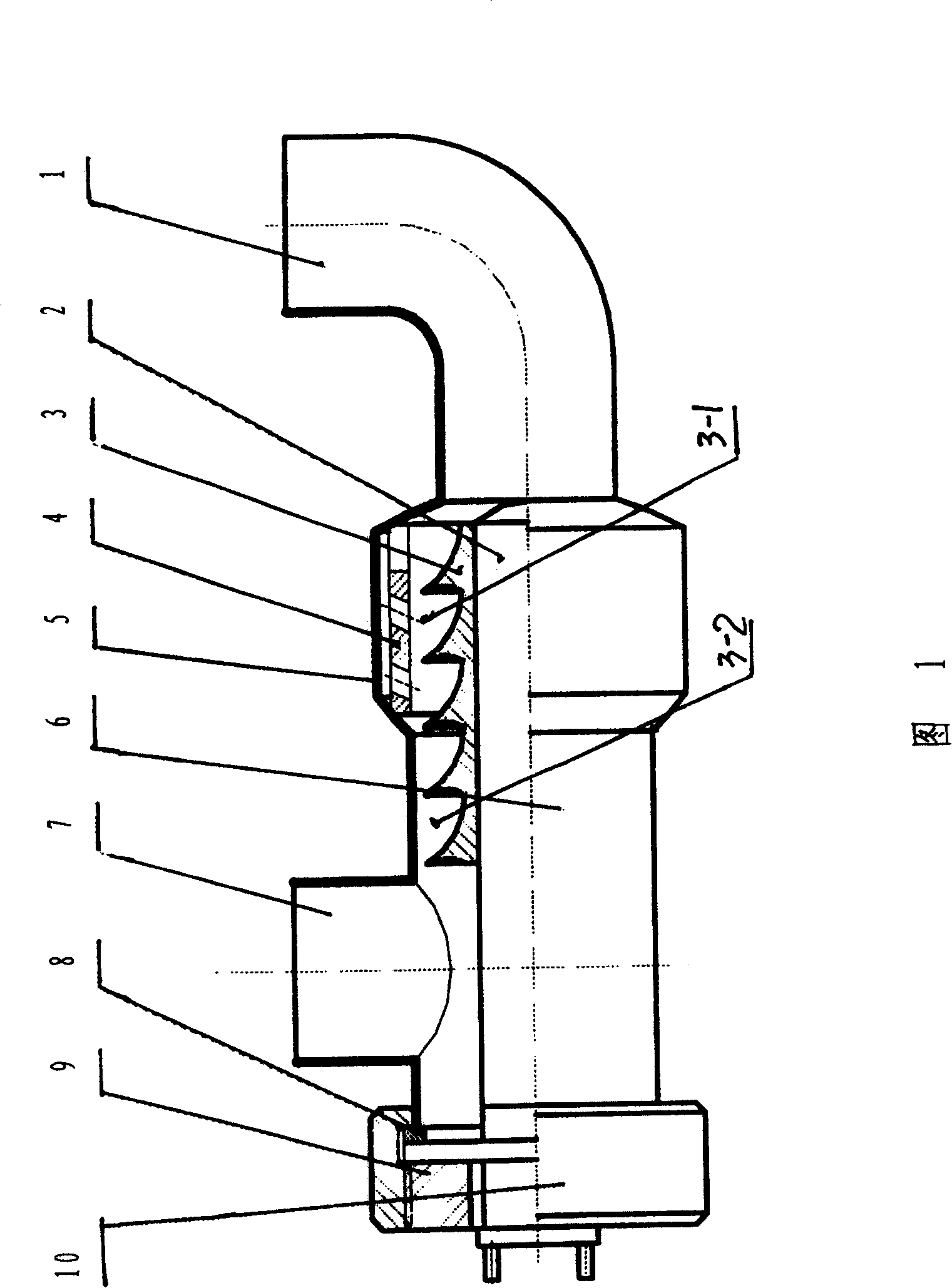
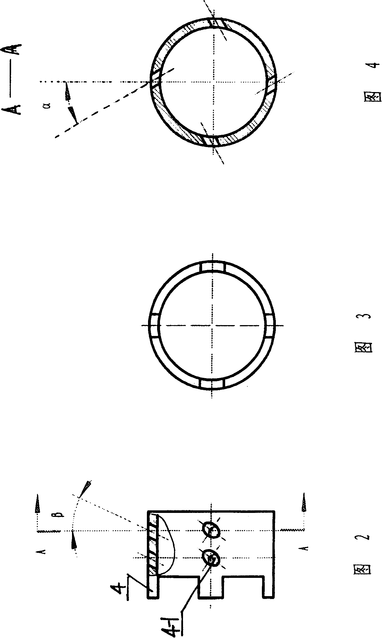
[0016] Embodiment: with reference to Fig. 1-Fig. 4. It can be seen from Fig. 1 that this is a heat pump whose heat source device is an electric heat source device. Here, the pump body consists of a radial guide housing 5 and an axial guide housing 6 . The electric heat source device 2 is located in the center of the pump body, its right half is located in the central hole of the axial flow guide 3, and the end of the left half extends out of the axial flow guide shell 6 and has a terminal. The end screw hole 10 is fixed on the left port of the axial guide housing 6. There is a circumferential groove in the end screw hole 10, and a rubber pad 8 which acts as a sealing medium is embedded in the groove, and passes through the end screw hole 10. The connected inner nut 9 is fixed. The medium outlet 7 is located on the side wall of the axial guide shell 6, the radial guide 4 is sleeved on the outside of the axial guide 3, and is covered in the radial guide shell 5, the radial gui...


PUM


Abstract

The invention relates to a thermal pump which is a energy exchange device used to transform heat energy into hydraulic energy directly to accelerate heat energy transfer and exchange. It includes pump body, heat source unit, axial diversion piece, medium inlet port and outlet port. The characteristic is that the heat source unit and the axial diversion piece are equipped orderly from inner to outer; radial diversion piece is equipped between the inside surface of pump body and axial diversion piece; the diversion series of the radial diversion piece is single stage at least. That can improve the ability of transforming heat energy into hydraulic energy directly, decrease heat energy waste, and improve the capacity factor; it also has no mechanical friction and noise.

Description

Technical field: [0001] The invention relates to a heat pump, which is an energy exchange device which directly converts heat energy into hydraulic energy and promotes heat energy transfer and exchange. The techniques it involves include molecular physics and statistical physics in thermal science, fluid mechanics and resistance science, etc. Its main theoretical basis is that any form of energy can be converted into each other. Background technique: [0002] At present, the devices used for energy conversion and transfer mainly include heat pumps, heat pipes, heat engines and mechanical pumps. Although they can transfer and convert energy, they all have the disadvantages of high energy consumption, high cost, complex structure, low energy exchange and transfer rate. Moreover, for some energy conversion and transfer devices, such as heat pipes, the medium cannot use chemically stable, low-cost, and non-polluting water, but only chemically unstable medium (such as Freon). O...

Claims


Application Information

Patent Timeline
Patent Type & Authority Patents(China)
IPC IPC(8): F04F11/00F04F1/06F04F3/00F04F99/00
Inventor 牟省先
Owner 牟省先
Why Eureka
Try Eureka