Negative voltage effective transmission circuit of standard logic process

An effective transmission and negative voltage technology, which is applied in logic circuits, electronic switches, electrical components, etc., can solve the problems of transmission gate on-resistance change, transmission gate initial voltage uncertainty, and negative voltage transmission quality. Consistency, the effect of reducing leakage

Active Publication Date: 2008-08-27
GIGADEVICE SEMICON (BEIJING) INC
View PDF3 Cites 2 Cited by
  • Summary
  • Abstract
  • Description
  • Claims
  • Application Information

AI Technical Summary

Problems solved by technology

At the same time, the initial state of the gate voltage of the transmission gate is controlled by a diode-connected transistor. This transistor is connected between the gate of the transmission gate and the negative voltage. This connection will cause the uncertainty of the initial voltage of the transmission gate, which is 0 volts. and a transistor threshold voltage that varies between
Uncertainty in the gate voltage of the transmission gate will cause a change in the on-resistance of the transmission gate, thereby affecting the transmission quality of negative voltages

Method used


Image

  • Negative voltage effective transmission circuit of standard logic process
  • Negative voltage effective transmission circuit of standard logic process

Examples


Embodiment Construction

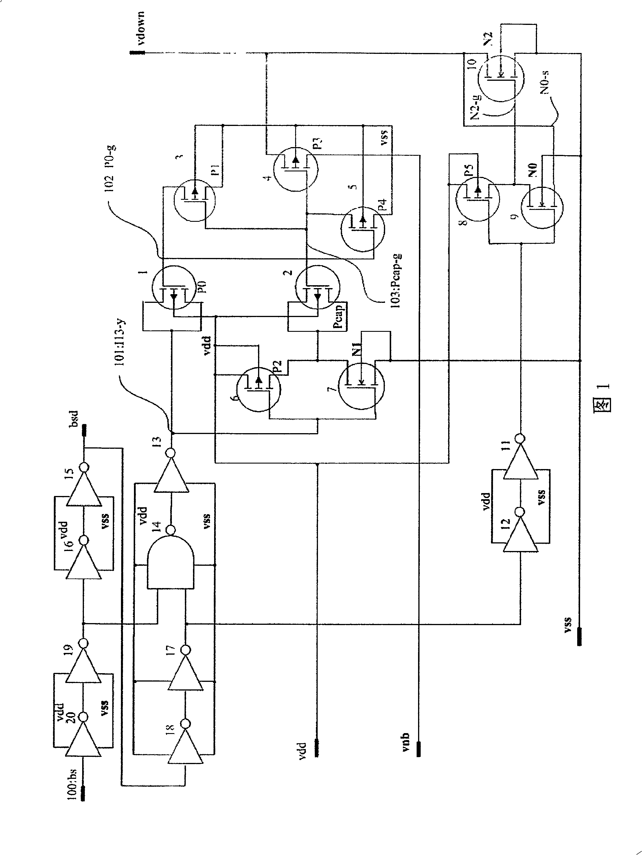
[0049] Referring to Fig. 1 first, the negative voltage effective transmission circuit of the present invention includes:

[0050] A clock circuit that alternately outputs high-level and low-level clock signals (composed of inverters 11 and 12, inverters 15 and 16, inverters 17 and 18, inverters 19 and 20, and inverters 13 and NOT gate 14, they constitute the delay buffer of the clock signal);

[0051]A low-voltage output channel (composed of transistors 8-10) that outputs a low voltage, its input is connected to the output of the clock circuit (that is, the output of the inverter 11), when the clock signal output by the clock circuit changes from high level to When it becomes a low level, the zero-voltage output channel is triggered to be turned on (that is, the transistor 10 is turned on, and the specific working process will be described below), and the low voltage vss is output;

[0052] A negative voltage output channel (composed of transistors 1-7) that outputs a negativ...


PUM


Abstract

This invention discloses a negative voltage effective transmission circuit on a standard logic technology including: a clock circuit outputting high level and low level clock signals alternately, a low voltage output channel outputting low voltages, the input of which is connected with said clock circuit output, when the clock signal output by the clock circuit is turned to low level from the high one, the low voltage output channel conduction is triggered to output the low voltage, a negative voltage output channel, the input of which is connected with the output of said clock circuit and the output of which is connected with the output of a zero voltage output channel as the output of the whole circuit, when the clock signal output by the clock circuit is turned to high level from the low, charges stored in a transistor playing the role of a couple condenser triggers the transmission gate conduction of said negative voltage output channel to output negative voltage.

Description

technical field [0001] The invention relates to an effective negative voltage transmission circuit suitable for a dynamic memory, in particular to an effective negative voltage transmission circuit on a standard logic process. Background technique [0002] For dynamic memories manufactured using standard logic processes, in order to reduce the subthreshold leakage into the transistor in the memory cell and maximize the stored charge in the storage capacitor, it is necessary to use a positive voltage higher than the power supply vdd and a negative voltage lower than the power supply ground vss. [0003] A standard logic process is a semiconductor chip manufacturing technology that provides only one layer of polysilicon, while providing a single-well or double-well structure. In the dynamic memory circuit, the positive voltage higher than the power supply vdd and the negative voltage lower than the power ground vss are transmitted to the word line through the word line driving...

Claims


Application Information

Patent Timeline
Patent Type & Authority Patents(China)
IPC IPC(8): H03K19/094H03K19/096H03K17/693
Inventor 朱一明
Owner GIGADEVICE SEMICON (BEIJING) INC
Why Eureka
Try Eureka