Shunting device and method

A shunt device and current technology, applied in the direction of adjusting electrical variables, control/regulation systems, instruments, etc., can solve the problems of high operating temperature, increased cost, inconvenience, etc., and achieve the effect of reducing operating temperature

Inactive Publication Date: 2008-09-24
SYST GEN
View PDF5 Cites 0 Cited by
  • Summary
  • Abstract
  • Description
  • Claims
  • Application Information

AI Technical Summary

Problems solved by technology

[0004] One of the first disadvantages of conventional regulators is the high operating temperature, especially when the input voltage is high
The second disadvantage is that the output current I 0 with the voltage drop across the series transistor 10 V D Generate power loss P D
The package determines the thermal resistance and limits its thermal radiation, while lower thermal resistance packages will increase the cost
[0005] This shows that the above-mentioned existing shunting device and method obviously still have inconvenience and defects in structure, method and use, and need to be further improved urgently
In order to solve the problems existing in voltage regulators, relevant manufacturers have tried their best to find a solution, but no suitable design has been developed for a long time, and general products do not have a suitable structure to solve the above problems, which is obvious. It is a problem that relevant industry players are eager to solve

Method used


Image

  • Shunting device and method
  • Shunting device and method
  • Shunting device and method

Examples


Embodiment Construction

[0048] In order to further explain the technical means and effects that the present invention adopts to achieve the intended purpose of the invention, below in conjunction with the accompanying drawings and preferred embodiments, the specific implementation, structure, method, steps, Features and their functions are described in detail below.

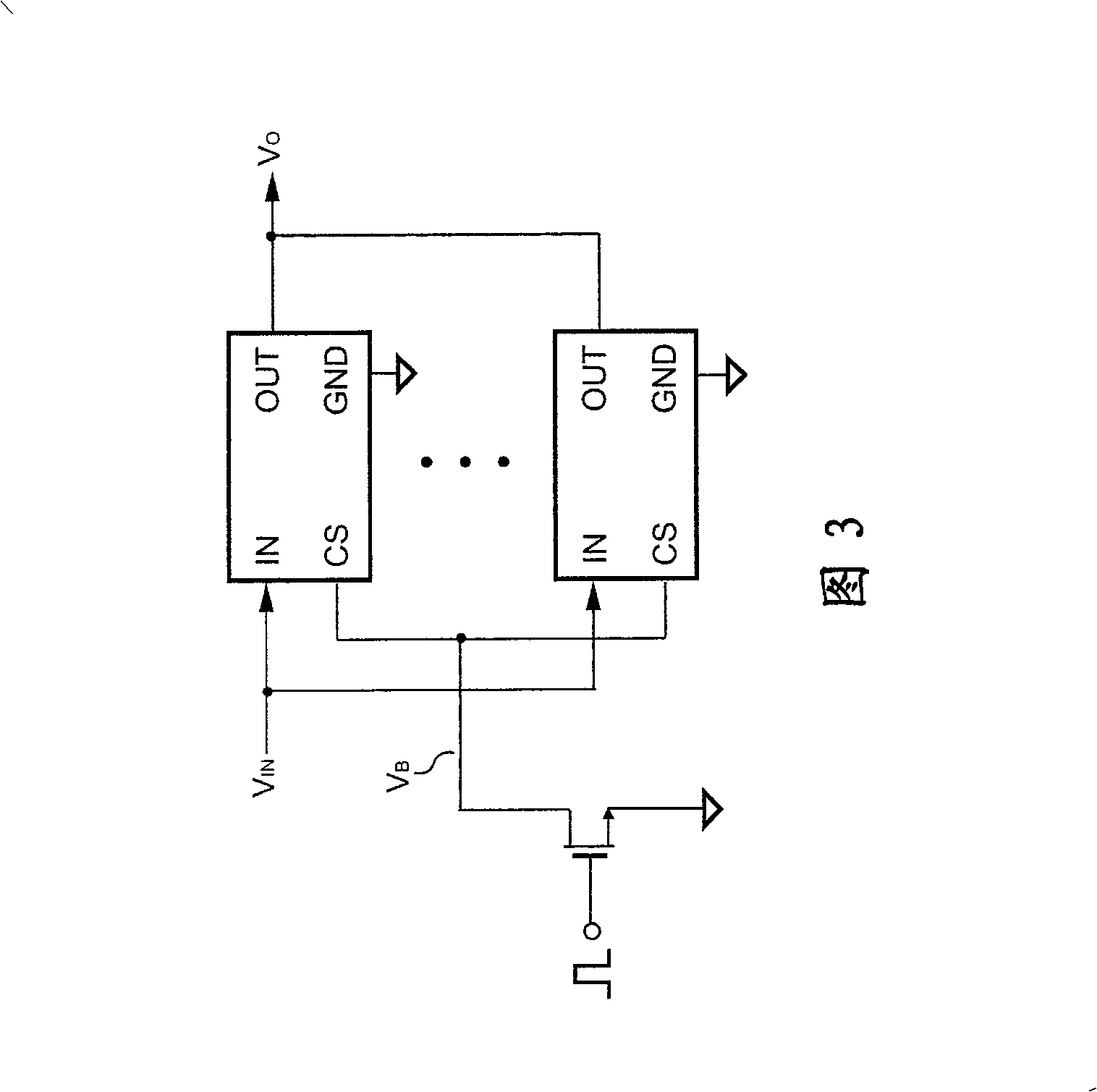
[0049] The present invention will use the following embodiments to illustrate the automatic control function of diversion by using the diversion control terminal of the diversion device. For the convenience of description, in the following embodiments, a voltage stabilizer will be used to represent the shunt device, and a voltage stabilizing device with multiple voltage stabilizers connected in parallel will be used to illustrate a preferred embodiment of the shunt device.

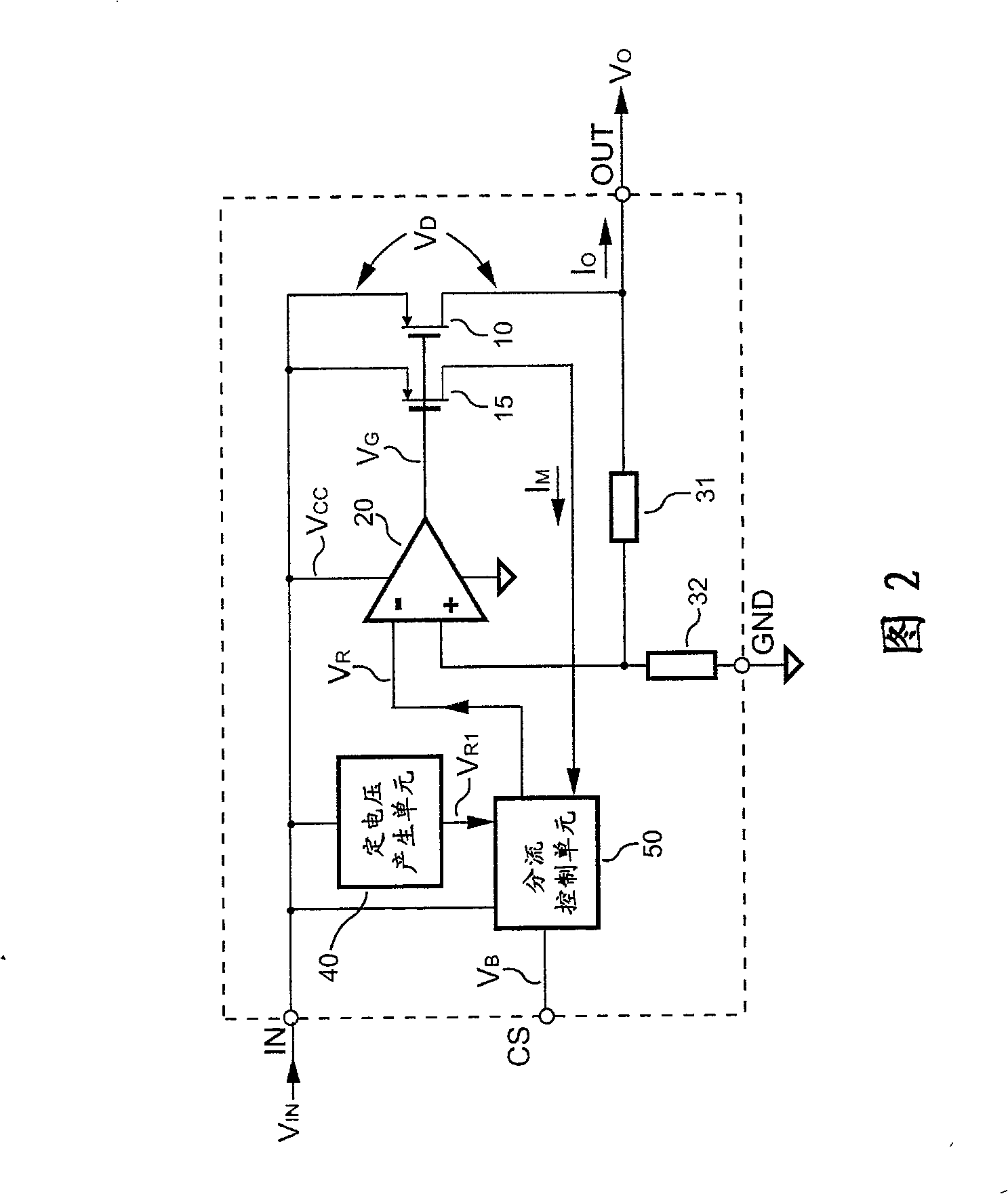
[0050] Please refer to FIG. 2 , which illustrates a preferred embodiment of a voltage regulator with shunt control function according to the present invention. The...


PUM


Abstract

A distributary device is prepared as using distributary control end to provide distributary control interface and using series - connected electric crystal to receive input end voltage, generating reference voltage by set voltage generation unit, coupling feedback circuit to distributary device and series - connected electric crystal for controlling output of distributary device and for outputting current detection signal, coupling distributary control unit to distributary device and feedback control circuit for generating bus bar signal and for generating reference signal according to reference voltage and bus bar signal as well as current detection signal.

Description

technical field [0001] The present invention relates to a flow diversion device and method, in particular to a flow diversion device and method which can automatically adjust respective diversion flow. Background technique [0002] The lifetime of a general component is closely related to its operating temperature. The greater the amount of current flowing through the element, the higher the operating temperature of the element will result. For example, when the input voltage to the regulator is high. The output current and voltage drop across the regulator produce power dissipation. This power dissipation causes the temperature of the regulator to rise. [0003] Voltage regulators are usually used in power management systems of various electrical products to provide adjustable power. Figure 1 is a typical circuit showing a voltage regulator. regulator consists of an unregulated DC input voltage V IN , output series transistor 10, adjustable DC output voltage V 0 and ...

Claims


Application Information

Patent Timeline
Patent Type & Authority Patents(China)
IPC IPC(8): G05F1/10
Inventor 杨大勇
Owner SYST GEN
Why Eureka
Try Eureka