Clutch based on ultrasonic suspending force control

A suspension force and clutch technology, applied in the field of clutches, can solve the problems of large clutch assembly size, low response speed, and susceptibility to electromagnetic interference, and achieve the effect of fast response speed, small volume and size, and no electromagnetic interference

Inactive Publication Date: 2008-10-08
HARBIN INST OF TECH
View PDF5 Cites 33 Cited by
  • Summary
  • Abstract
  • Description
  • Claims
  • Application Information

AI Technical Summary

Problems solved by technology

[0002] At present, there are many types of clutches used between miniature and high-speed rotating shafts. Although each has its own unique characteristics, they are basically designed using electromagnetic principles or mechanical principles, so there are the following defects: 1. The response speed is not high. ; 2. Susceptible to electromagnetic interference and unstable movement; 3. Large clutch and assembly size

Method used


Image

  • Clutch based on ultrasonic suspending force control
  • Clutch based on ultrasonic suspending force control
  • Clutch based on ultrasonic suspending force control

Examples


specific Embodiment approach 1

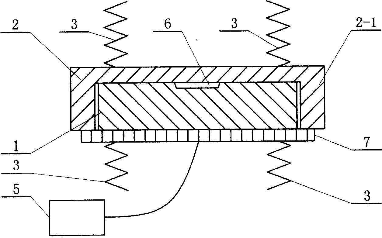
[0007] Specific implementation mode one: the following combination figure 1 This embodiment will be specifically described. This embodiment consists of an active rotating disk 2, a passive rotating disk 1, a piezoelectric ceramic sheet 7, a return spring 3 and a high-frequency power supply 5. The active rotating disk 2 and the passive rotating disk 1 have the same rotation axis, and the passive rotating disk 1 Fastened in the ring body 2-1 of the active rotating disk 2, the end surface of the active rotating disk 2 is in contact with the inner end surface of the passive rotating disk 1, and the piezoelectric ceramic sheet 7 is fixed on the outer end surface of the passive rotating disk 1. The frequency power supply 5 is connected to the terminal of the piezoelectric ceramic sheet 7, and the return spring 3 is arranged on the active rotating disk 2 or the passive rotating disk 1 to keep the active rotating disk 2 and the passive rotating disk 1 in contact. The return spring 3 ...

specific Embodiment approach 2

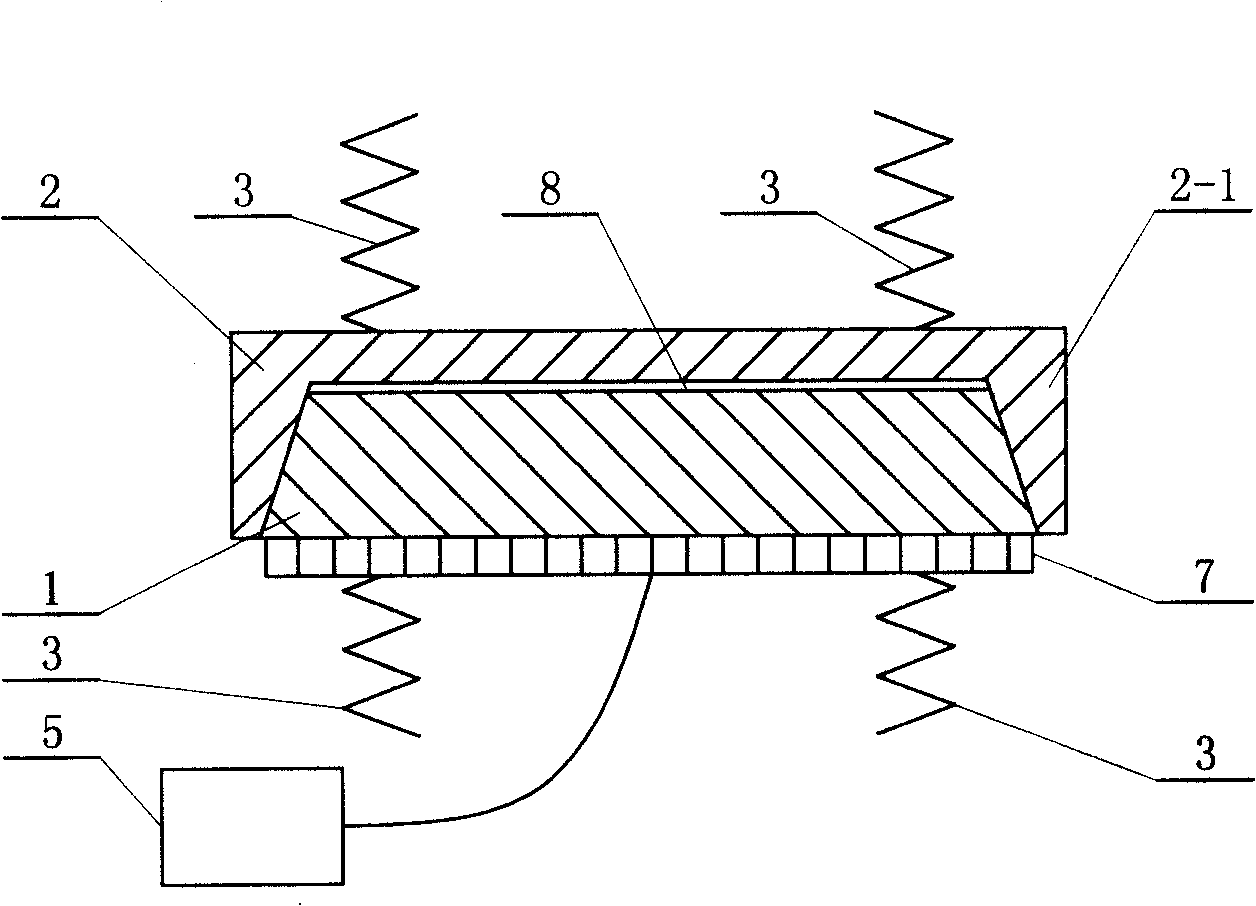
[0019] Specific implementation mode two: the following combination figure 2 This embodiment will be specifically described. This embodiment consists of an active rotating disk 2, a passive rotating disk 1, a piezoelectric ceramic sheet 7, a return spring 3 and a high-frequency power supply 5. The active rotating disk 2 and the passive rotating disk 1 have the same rotation axis, and the passive rotating disk 1 Fastened in the torus 2-1 of the active rotating disk 2, the inner surface of the torus 2-1 is conical, the rim of the passive rotating disk 1 is conical, and the inner surface of the torus 2-1 is conical. The rims of the passive rotating disk 1 are in contact, the piezoelectric ceramic sheet 7 is fixed on the outer end surface of the passive rotating disk 1, the high-frequency power supply 5 is connected to the terminal of the piezoelectric ceramic sheet 7, and the return spring 3 is arranged on the active rotating disk 2 or on the passive rotating disk 1 to keep the ...


PUM


Abstract

The invention discloses a clutch based on ultrasonic suspending force control, which is composed of active rotating disc, passive rotating disc, piezoelectric ceramic piece, back-moving spring and high-frequency electric source. The passive rotating disc couples to the circular ring of the active rotating disc. The end face of the active rotating disc contacts to an end face of the passive rotating disc. The piezoelectric ceramic piece is fixed on the other end face of the passive rotating disc. The high-frequency electric source connects to the receiving terminal of the piezoelectric ceramic piece. The back-moving spring is set on active rotating disc or passive rotating disc to keep a certain distance between the active rotating disc and passive rotating disc. Another embodiment is that: the inner surface of the circular ring 2-1 is taper shaped; the flange of 1 is taper shaped; the inner surface of the 2-1 contacts to the flange of 1. The invention applies the ultrasonic suspending force as drive force for separation and applies friction moment to transmit power.

Description

Technical field: [0001] The invention relates to a clutch for a miniature high-speed rotating shaft using the principle of ultrasonic suspension. Background technique: [0002] At present, there are many types of clutches used between miniature and high-speed rotating shafts. Although each has its own unique characteristics, they are basically designed using electromagnetic principles or mechanical principles, so there are the following defects: 1. The response speed is not high. ; 2. Susceptible to electromagnetic interference and unstable movement; 3. The size of the clutch and assembly is large. Invention content: [0003] In order to overcome electromagnetic interference, increase response speed and reduce size, the present invention provides a clutch based on ultrasonic levitation force control. The clutch can not only be used in occasions with electromagnetic interference, but also can be applied to high-speed miniature shafts with high requirements for start-stop r...

Claims


Application Information

Patent Timeline
Patent Type & Authority Patents(China)
IPC IPC(8): F16D28/00H02N2/00F16D13/38F16D13/71F16D27/00
Inventor 曲建俊李艳张坤宋宝玉
Owner HARBIN INST OF TECH
Why Eureka
Try Eureka