Voltage reference circuit

A voltage reference and circuit technology, applied in the field of programmable voltage reference circuits, can solve problems such as consumption, large chip area, and large DC power consumption, and achieve the effects of simple implementation, low static power consumption, and low DC power consumption

Active Publication Date: 2008-10-22
SEMICON MFG INT (SHANGHAI) CORP +1
View PDF8 Cites 2 Cited by
  • Summary
  • Abstract
  • Description
  • Claims
  • Application Information

AI Technical Summary

Problems solved by technology

However, the bandgap circuit itself has a serious disadvantage: the bandgap reference circuit itself usually consumes relatively large DC power consumption. In addition, in order to obtain the required voltage, a voltage divider is also required. These two modules usually need to draw 10 to

Method used


Image

  • Voltage reference circuit
  • Voltage reference circuit
  • Voltage reference circuit

Examples


Embodiment Construction

[0018] In the following detailed description of the invention, numerous specific details are set forth in order to provide a thorough understanding of the invention. In other instances, well-known methods, procedures, components, and circuits are not described in detail to avoid obscuring the main content of the present invention. It will be apparent, however, to one skilled in the art that the present invention may be practiced without these specific details. The present invention will be described below with reference to specific examples.

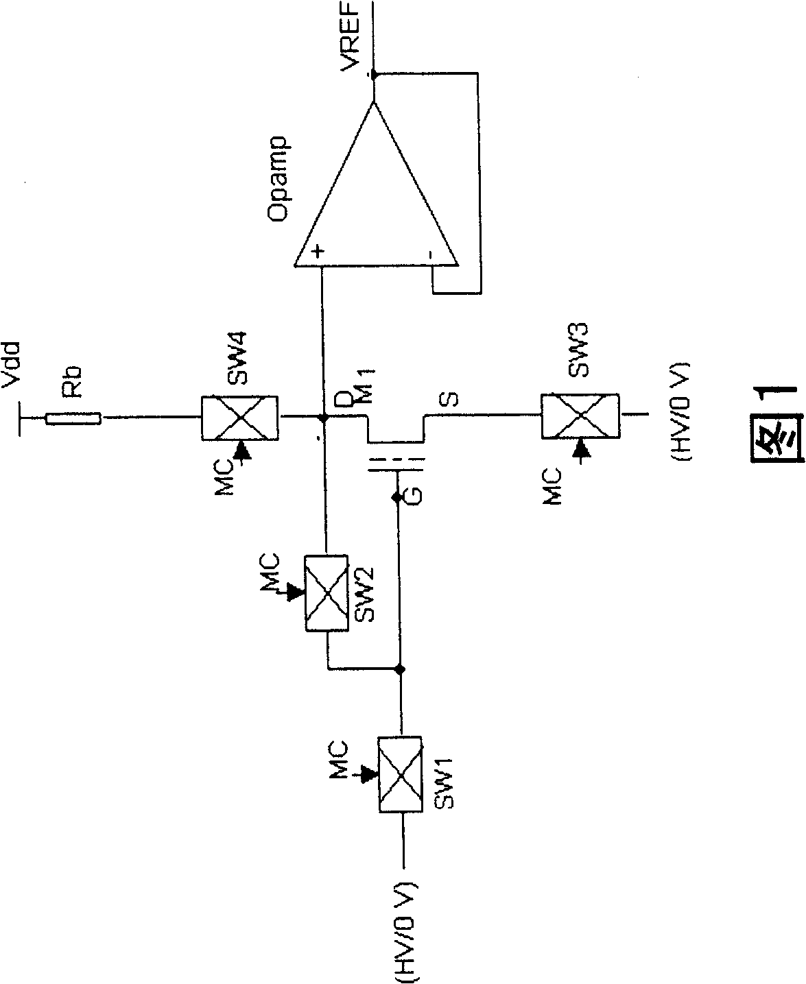
[0019] FIG. 1 is a schematic circuit diagram of the first embodiment of the present invention. In the circuit shown in Figure 1, it includes an EEPROM cell M1, which has a floating gate region, a drain, a gate and a source, and the floating gate region stores charges, and the threshold voltage of M1 depends on the stored charge in the floating gate region. The amount of charge, resistor Rb, SW1 to SW4 are switching devices for selectiv...


PUM


Abstract

The present invention discloses a programmable reference voltage circuit. The voltage reference circuit provided by said invention can be implemented by using EEPROM unit. It utilizes the characteristics that the charge stored in its floating gate zone can influence its threshold voltage, and said invented programmable reference voltage circuit has the advantages of low DC power consumption and programmable regulated output voltage, etc.

Description

technical field [0001] The present invention generally relates to a voltage reference circuit used in a semiconductor integrated device. More particularly, the present invention relates to a programmable voltage reference circuit implemented with EEPROM cells for use in semiconductor integrated devices. Background technique [0002] Reference voltage generating circuits are required in various semiconductor devices, especially nonvolatile memory devices. In the prior art, a bandgap reference circuit is often used to generate a stable reference voltage. For example, US Patent Nos. 6,570,437, 6,566,850 and 6,563,371 respectively show circuits and methods for generating voltage using bandgap circuits. However, the bandgap circuit itself has a serious disadvantage: the bandgap reference circuit itself usually consumes relatively large DC power consumption. In addition, in order to obtain the required voltage, a voltage divider is also required. These two modules usually need t...

Claims


Application Information

Patent Timeline
IPC IPC(8): G05F1/10G05F3/02
Inventor 许丹罗文哲
Owner SEMICON MFG INT (SHANGHAI) CORP
Why Eureka
Try Eureka