Supercharge Your Innovation With Domain-Expert AI Agents!

Decoder for decoding and re-establishing multiple audio track andio signal from audio data code stream

A technology of audio signal and audio data, applied in the direction of pulse modulation TV signal transmission, code conversion, high-definition TV system, etc. The effect of computation

Inactive Publication Date: 2008-11-19
广州广晟数码技术有限公司
View PDF6 Cites 0 Cited by
  • Summary
  • Abstract
  • Description
  • Claims
  • Application Information

AI Technical Summary

Problems solved by technology

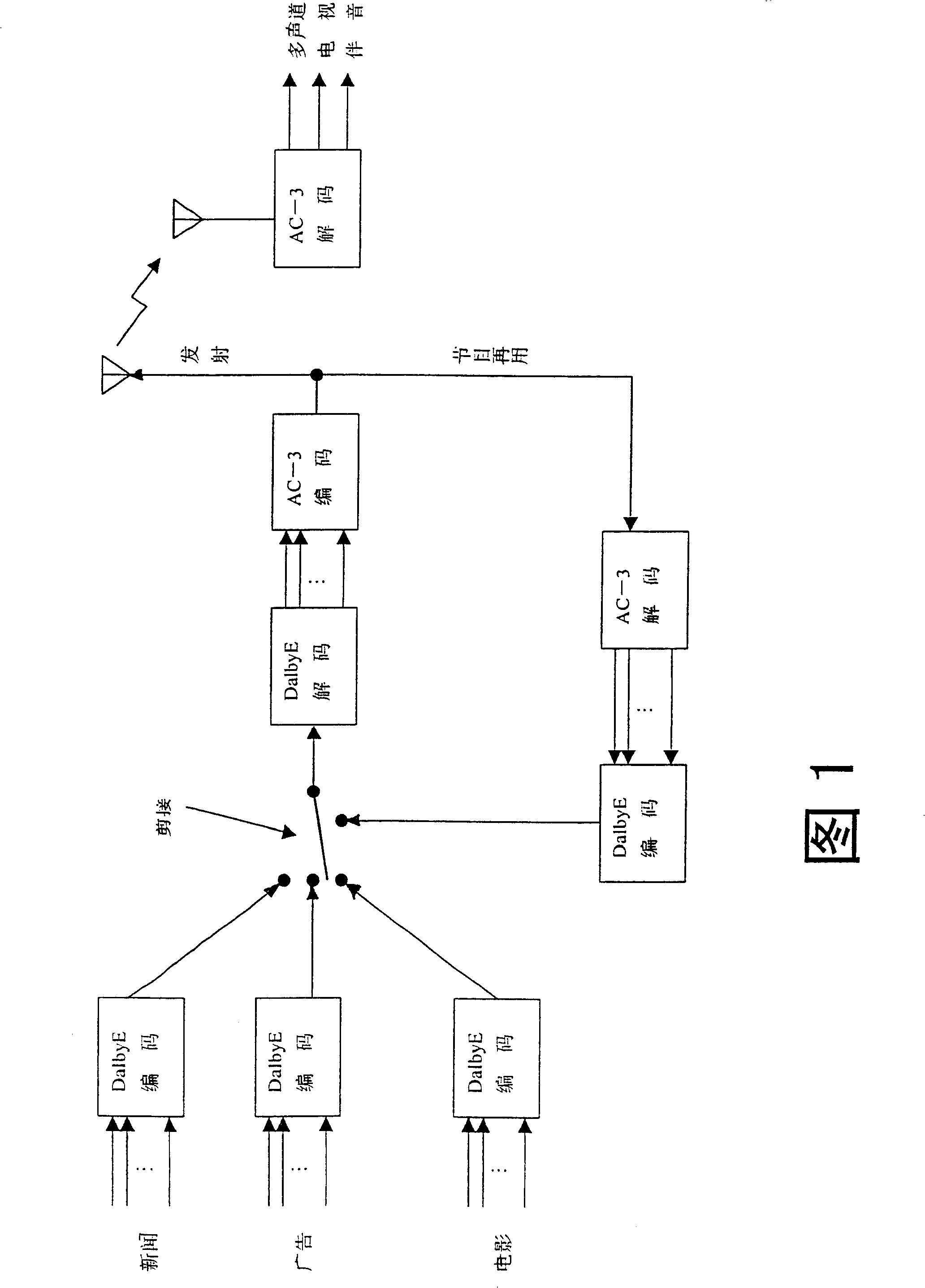
It can be seen from the above that there are several difficulties in this TV station method: 1) The distortion of the audio signal is large: the sampling rate conversion of Dolby E itself introduces distortion, and the code stream from the Dolby E format to the code stream of the AC-3 format is transferred Encoding (Transcoding) introduces new distortion
2) The programs that have been transmitted are difficult to reuse: as shown in Figure 1, if the programs that have been transmitted are to be reused, they must be decoded into PCM and encoded by Dolby E before they can be switched with other programs (such as advertisements, etc.)
Since the code rate for the final transmission is generally not high, the sound quality of the transmitted programs after the above series of transfer encoding (AC-3 decoding -> Dolby E encoding -> Dolby E decoding -> AC-3 encoding) is very low. difficult or impossible to guarantee
3) Since the sampling rate of Dolby E's input and output has no simple frequency multiplication relationship, its encoding and decoding are very complicated and expensive

Method used


Image

  • Decoder for decoding and re-establishing multiple audio track andio signal from audio data code stream
  • Decoder for decoding and re-establishing multiple audio track andio signal from audio data code stream
  • Decoder for decoding and re-establishing multiple audio track andio signal from audio data code stream

Examples


Embodiment 1

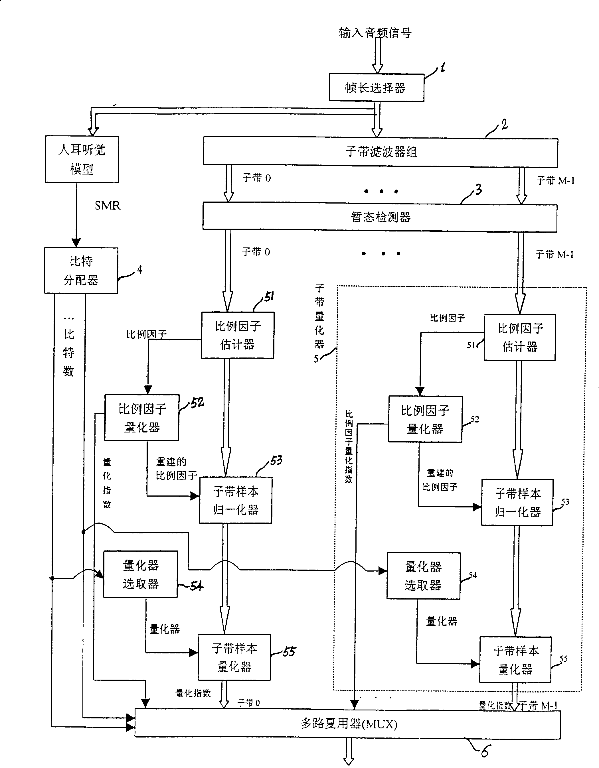
[0042] Such as figure 2 As shown, the encoder of the present invention is composed of a frame length selector 1, a sub-band decomposition filter bank 2, a transient detector 3, a bit allocator 4, a sub-band quantizer 5, and a multiplexer 6. It is used to compress and encode the input audio signal. The audio signal may be an audio signal of a digital television. The following describes the working principle of the encoder through a detailed description of each component.

[0043] Frame length selector 1:

[0044] The function of the frame length selector 1 is to divide the input audio signal into frames according to a certain frame length. As for the choice of frame length, it is generally believed that the larger the frame length, the higher the encoding compression efficiency, but the greater the encoding delay, the greater the demand for memory units by the encoder and decoder. Therefore, when the code rate is high, a smaller frame length is generally selected, and whe...

Embodiment 2

[0088] The encoder of the second embodiment of the present invention is as Figure 4 shown. Most of its components are the same as those in Embodiment 1, the difference lies in the unique bit allocation method of this embodiment. Specifically, the bit allocation in this embodiment is not as in Embodiment 1 to allocate bits for each subband segment according to the signal-to-noise ratio (SNR) or the signal-to-coverage ratio (SMR), but according to the scale factor quantizer 52 output The quantization index of the scale factor uses the following formula to allocate bits for each subband segment.

[0089] b(c,k,d)=f(α·s(c,k,d))-θ(k)-β (3)

[0090] in:

[0091] 1) b(c, k, d) is the number of bits per sample allocated to the current subband segment.

[0092] 2) f(α·s(c, k, d)) is a strictly monotonically increasing function. It can preferably be set as f(α·s(c,k,d))=[α·s(c,k,d)] q , where 0

[0093] 3) θ...

Embodiment 3

[0110] The encoder of the third embodiment of the present invention is as Image 6 shown. Most of its components are the same as those of other embodiments, the difference is that this embodiment has one more joint strength encoder 7 than other embodiments. The theoretical basis of joint intensity coding is that the human ear's spatial localization of sound at high frequencies (such as above 7 kHz) is mainly based on the intensity of the sound. Such as Image 6 As shown, when encoding, the joint intensity encoder 7 can add up the high-frequency subbands output by the transient detector 3 of the left and right (or other joint) channels, and only pass this sum subband (referred to as the source sound The quantization index of each sample of the jointly coded subband of the channel is added to the intensity index of the combined subband of the channel to achieve the purpose of saving bits.

[0111] When joint intensity coding is used, the allocation of bits to jointly coded su...


PUM


Abstract

This invention relates to a device and a method for carrying out compressed encode and decode, among which, the encode device includes a frame length selector, a sub-band dissociated filter, a transient state detector, a proportional factor evaluator, a bit distributor used in adaptively distributing the bit resource decided by the target code rate to each sub-band, a sub-band quantiser and a multiplexer. The audio signals encoded by this invention can be edited synchronously with video signals and can endure over ten times of column codes so as to meet the needs of program distribution and transmission and reduce the processes and devices of program distribution greatly.

Description

[0001] This application is a divisional application submitted on August 21, 2002, with application number 02130245.6. technical field [0002] The present invention relates to a digital audio signal encoding / decoding device and its method, more precisely, to a multi-channel digital audio signal compression encoding / decoding device and method. Background technique [0003] Multi-channel (including stereo) digital audio compression coding technology has been widely used in VCD, SVCD, DVD, satellite TV, digital TV, and Internet (Internet) and other fields. The main problem it needs to solve is that the code rate for expressing multi-channel digital audio signals is very high, but the channel capacity that can be used to propagate or store it is very limited. For example, using PCM to express 5.1-channel surround sound with 48kHz sampling rate and 24 bits per sample requires a code rate of 6912kbps (kilobits per second), and applications with limited channel capacity such as dig...

Claims


Application Information

Patent Timeline
IPC IPC(8): H03M7/30H04N7/015H04N7/24
Inventor 游余立
Owner 广州广晟数码技术有限公司
Features
  • R&D
  • Intellectual Property
  • Life Sciences
  • Materials
  • Tech Scout
  • Unparalleled Data Quality
  • Higher Quality Content
  • 60% Fewer Hallucinations
Learn More