Coding method for compressing coding of multiple audio track audio signal
A coding method and digital audio technology, applied in the direction of pulse modulation TV signal transmission, code conversion, high-definition TV system, etc., can solve the problems of complex and expensive coding and decoder, difficult sound quality, difficult to reuse, etc., to reduce computing power volume effect
- Summary
- Abstract
- Description
- Claims
- Application Information
AI Technical Summary
Problems solved by technology
Method used
Image

Examples
Embodiment 1
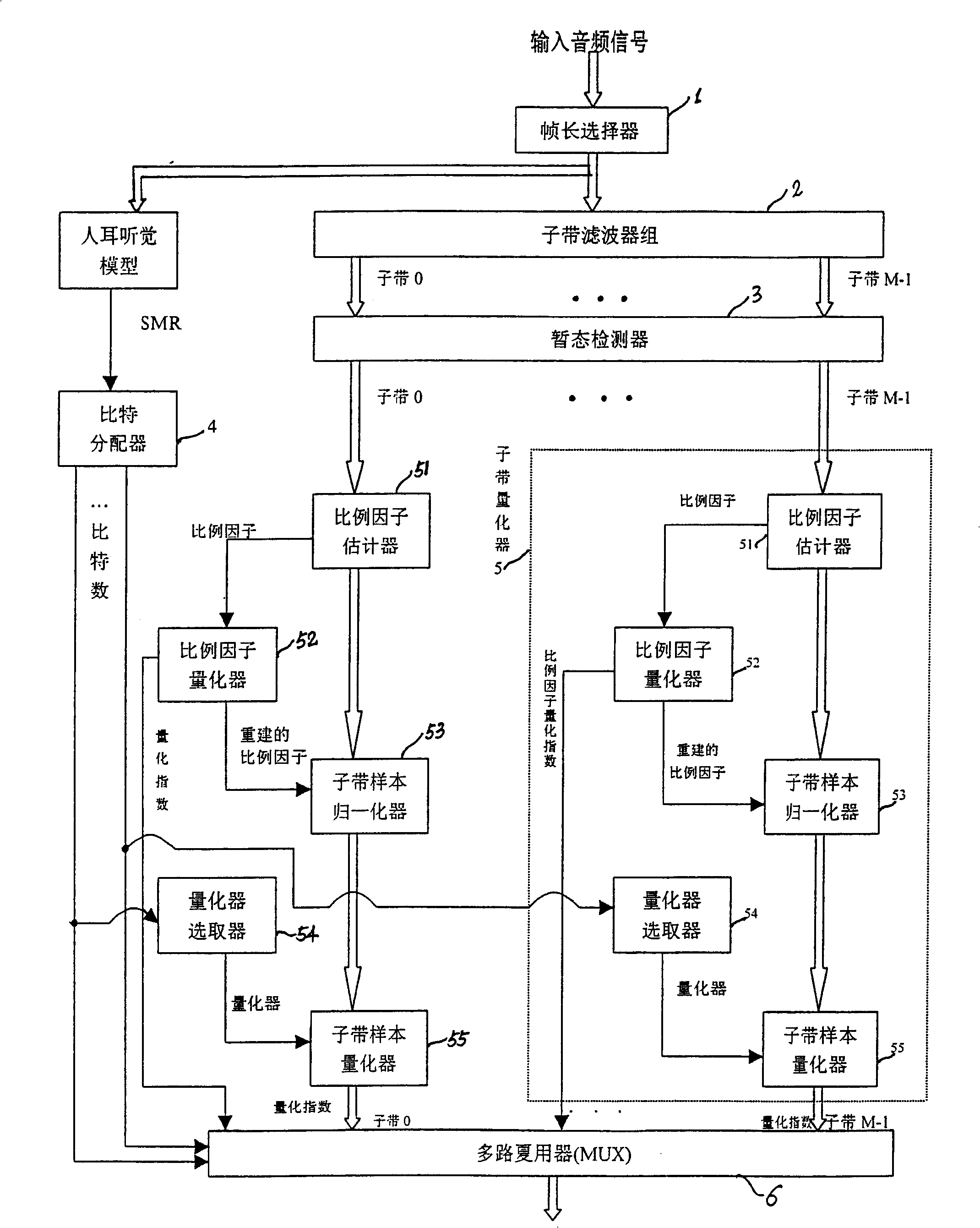
[0042] Such as figure 2 As shown, the encoder of the present invention is composed of a frame length selector 1, a sub-band decomposition filter bank 2, a transient detector 3, a bit allocator 4, a sub-band quantizer 5, and a multiplexer 6. It is used to compress and encode the input audio signal. The audio signal may be an audio signal of a digital television. The following describes the working principle of the encoder through a detailed description of each component.
[0043] Frame length selector 1:
[0044] The function of the frame length selector 1 is to divide the input audio signal into frames according to a certain frame length. As for the choice of frame length, it is generally believed that the larger the frame length, the higher the encoding compression efficiency, but the greater the encoding delay, the greater the demand for memory units by the encoder and decoder. Therefore, when the code rate is high, a smaller frame length is generally selected, and whe...
Embodiment 2
[0088] The encoder of the second embodiment of the present invention is as Figure 4 shown. Most of its components are the same as those in Embodiment 1, the difference lies in the unique bit allocation method of this embodiment. Specifically, the bit allocation in this embodiment is not as in Embodiment 1 to allocate bits for each subband segment according to the signal-to-noise ratio (SNR) or the signal-to-coverage ratio (SMR), but according to the scale factor quantizer 52 output The quantization index of the scale factor uses the following formula to allocate bits for each subband segment.
[0089] b(c,k,d)=f(α·s(c,k,d))-θ(k)-β(3)
[0090] in:
[0091] 1) b(c, k, d) is the number of bits per sample allocated to the current subband segment.
[0092] 2) f(α·s(c, k, d)) is a strictly monotonically increasing function. It can preferably be set as f(α·s(c,k,d))=[α·s(c,k,d)] q , where 0
[0093] 3) θ(...
Embodiment 3
[0110] The encoder of the third embodiment of the present invention is as Image 6 shown. Most of its components are the same as those of other embodiments, the difference is that this embodiment has one more joint strength encoder 7 than other embodiments. The theoretical basis of joint intensity coding is that the human ear's spatial localization of sound at high frequencies (such as above 7 kHz) is mainly based on the intensity of the sound. Such as Image 6 As shown, when encoding, the joint intensity encoder 7 can add up the high-frequency subbands output by the transient detector 3 of the left and right (or other joint) channels, and only pass this sum subband (referred to as the source sound The quantization index of each sample of the jointly coded subband of the channel is added to the intensity index of the combined subband of the channel to achieve the purpose of saving bits.
[0111] When joint intensity coding is used, the allocation of bits to jointly coded su...
PUM
 Abstract
Description
Claims
Application Information
 - R&D
- Intellectual Property
- Life Sciences
- Materials
- Tech Scout
- Unparalleled Data Quality
- Higher Quality Content
- 60% Fewer Hallucinations
Browse by: Latest US Patents, China's latest patents, Technical Efficacy Thesaurus, Application Domain, Technology Topic, Popular Technical Reports.
© 2025 PatSnap. All rights reserved.Legal|Privacy policy|Modern Slavery Act Transparency Statement|Sitemap|About US| Contact US: help@patsnap.com