Current limiter for short circuit fault

A short-circuit fault, current limiter technology, applied in circuit devices, emergency protection circuit devices, protection against overcurrent, etc., can solve the problems of technical difficulty and high cost of bias power supply, and eliminate steady-state current waveform distortion. , Guarantee power quality, improve the effect of current limiting effect

Inactive Publication Date: 2008-12-03
INST OF ELECTRICAL ENG CHINESE ACAD OF SCI
View PDF5 Cites 0 Cited by
  • Summary
  • Abstract
  • Description
  • Claims
  • Application Information

AI Technical Summary

Problems solved by technology

However, the current flowing through the bias power supply is often 2 to 3 times the grid current, and must meet the requirements of the current change in the non-fault state and the fault state. Therefore, the realization of the bias power supply has certain technical difficulties and high requirements. cost

Method used


Image

  • Current limiter for short circuit fault
  • Current limiter for short circuit fault
  • Current limiter for short circuit fault

Examples


Embodiment Construction

[0022] The present invention will be further described below in conjunction with accompanying drawing and specific embodiment:

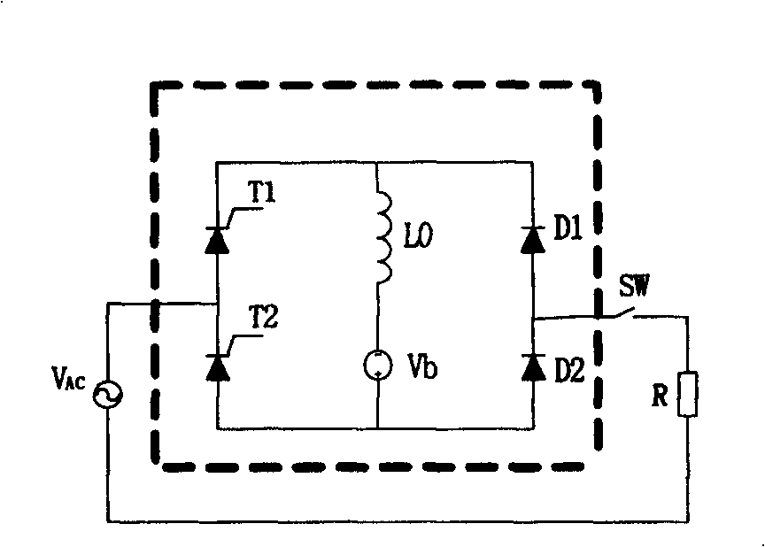
[0023] Such as figure 2As shown, Embodiment 1 of the present invention is a single-phase short-circuit fault current limiter. The existing single-phase short-circuit fault current limiter is composed of a single-phase rectifier bridge composed of a first thyristor T1, a second thyristor T2, a first diode D1, and a second diode D2, and a current-limiting inductance L0. On this basis, the first capacitor C1 and the second capacitor C2 are respectively connected in series at the positive and negative DC ends of the rectifier bridge, and the current-limiting inductance L0 in the existing short-circuit fault current limiter is formed by the first current-limiting inductance (general inductance or super Conductive inductance can be replaced by L1 and the second current-limiting inductance L2, the connection point of the first thyristor T1 and the second ...


PUM


Abstract

The disclosed current limiter for short circuit fault is constituted by adding a cascaded capacitor to positive / negative DC ends of rectification bridge of existed current limiter for short circuit fault respectively; two capacitors and two current limiting inductances are connected in shape of number '8'. The disclosed current limiter can restrict peak value of fault current, restrict ascending velocity of fault current at any time, improves distortion of stable current generated by current limiter. Under condition of canceling bias voltage, size and cost can be reduced. Based on connection method of existed current limiter for short circuit fault, the invention can constitute multiple circuit structures. Advantages are: simple structure, high current limiting capacity, raised quality, stability, safety and reliability of power network.

Description

technical field [0001] The invention relates to a short-circuit fault current limiter, in particular to a fault current limiter for transmission and distribution networks. Background technique [0002] With the rapid development of the national economy, the society's demand for electricity continues to increase, which drives the continuous development of the power system. The capacity of single machines and power plants, the capacity of substations, and the load of cities and industrial centers continue to increase, which makes the interconnection of power systems , the level of short-circuit current in the power grid at all levels is increasing continuously, and the destructiveness of short-circuit faults to the power system and its connected electrical equipment is also increasing. Moreover, while the demand for electric energy is increasing day by day, people also put forward higher requirements for power quality, power supply reliability and security. However, the trans...

Claims


Application Information

Patent Timeline
Patent Type & Authority Patents(China)
IPC IPC(8): H02H9/02H02H7/26H02H3/08
Inventor 张志丰肖立业
Owner INST OF ELECTRICAL ENG CHINESE ACAD OF SCI
Why Eureka
Try Eureka