Evaporation pipe type miniature-small-sized engine combustion chamber

A technology of combustion chamber and evaporation tube, which is applied in the direction of combustion chamber, continuous combustion chamber, combustion method, etc. It can solve the problems of long flame, low evaporation rate of evaporation tube, and low combustion efficiency of combustion chamber, so as to achieve uniform distribution of oil and gas and improve evaporation The effect of improving the rate and combustion efficiency

Inactive Publication Date: 2008-12-17
BEIHANG UNIV
View PDF3 Cites 1 Cited by
  • Summary
  • Abstract
  • Description
  • Claims
  • Application Information

AI Technical Summary

Problems solved by technology

Multiple Γ-shaped evaporating tubes are welded to the front wall of the flame tube, and the direct injection fuel nozzle sprays fuel into the Γ-shaped evaporating tubes along the axial direction. The combustion efficiency is low; the main combustion zone of the combustion chamber is behind, and the stable flame mode of multiple small jets leads to a longer flame

Method used


Image

  • Evaporation pipe type miniature-small-sized engine combustion chamber
  • Evaporation pipe type miniature-small-sized engine combustion chamber
  • Evaporation pipe type miniature-small-sized engine combustion chamber

Examples


Embodiment Construction

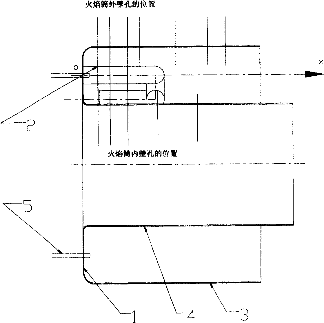
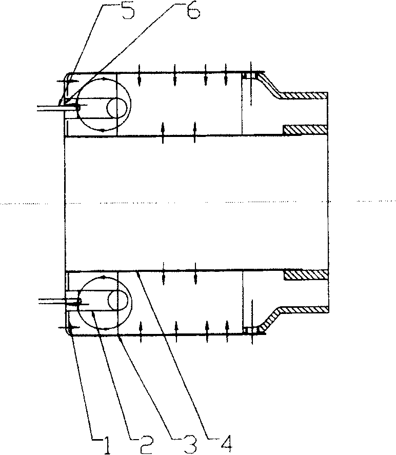
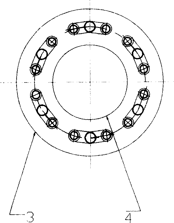
[0021] Such as figure 2 , 3 As shown, the present invention is composed of the inner wall 4 and the outer wall 3 of the combustion chamber flame tube, 3-12 T-shaped evaporation tubes 2, and fuel nozzles 5. Evenly arranged, 3-12 fuel nozzles 5 are inserted into 3-12 T-shaped evaporation tubes in the radial direction, and a plurality of holes 6 are punched on the inner wall 4, outer wall 3 and front end wall 1 of the combustion chamber flame tube, the number of holes and The aperture is determined by the gas volume distribution of the combustion chamber and the circumferential size of the flame cylinder in the combustion chamber. If a position with a large volume is required, the aperture is relatively large, and the size is determined by the circumference of the flame cylinder. How big and how much can be drilled. The ratio of the sum of the hole area to the total opening area should be consistent with the gas volume distribution at this place, and the general quantity is sho...


PUM


Abstract

The combustion chamber of the evaporating tube type micro engine is composed of the inner and outer walls of the combustion chamber flame tube, 3-12 T-shaped evaporation tubes, and fuel nozzles. The 3-12 T-shaped evaporation tubes are evenly arranged along the circumference of the front wall of the combustion chamber flame tube. , 3-12 fuel nozzles are inserted radially into 3-12 T-shaped evaporator tubes, and a number of holes are punched on the inner wall, outer wall and front end wall of the combustion chamber flame tube, and the air flows from the inner wall, outer wall and front end wall of the combustion chamber flame tube The wall enters the combustion chamber, and a stable single large vortex is formed at the head of the flame tube by tangential air intake. The invention makes the mixing with air more uniform, and the combustion is more stable; the combustion structure of the main combustion zone is limited by the size of the micro-fired combustion chamber, and a large vortex is used to stabilize the flame; the overall design advances the main combustion zone of the combustion chamber and shortens the length of the combustion chamber .

Description

Technical field [0001] The invention relates to a combustion system of a miniature aeroengine, in particular to an evaporating tube type miniature engine combustion chamber. Background technique [0002] At present, a lot of research work has been done on micro-engines in foreign countries, and a lot of results have been obtained. Mature models of various magnitudes have been produced correspondingly, and considerable military and civilian markets have been formed. AMT in the Netherlands, Rolls-Royce in the UK, and Artesjet all have a series of products, such as AMT's Mercury HP and Pegasus HP, and Artesjet's KJ66. The structure of the combustion chamber of a certain type of micro engine is as follows: figure 1 As shown, it is composed of the front wall 1 of the combustion chamber, the inner wall 4 of the flame tube, the outer wall 3 of the flame tube, the evaporation tube 2 and the fuel nozzle 5, wherein the evaporation tube 2 is composed of a plurality of Γ-shaped evapora...

Claims


Application Information

Patent Timeline
Patent Type & Authority Patents(China)
IPC IPC(8): F23R3/58F23R3/02
Inventor 林宇震刘俊
Owner BEIHANG UNIV
Why Eureka
Try Eureka