Multiple optical axises photoelectric sensor

A photoelectric sensor, multi-optical axis technology, applied in the direction of instruments, circuits, electric switches, etc., to achieve the effect of preventing adverse situations

Inactive Publication Date: 2008-12-17
PANASONIC INDAL DEVICES SUNX
View PDF7 Cites 0 Cited by
  • Summary
  • Abstract
  • Description
  • Claims
  • Application Information

AI Technical Summary

Problems solved by technology

In this configuration, the shading detection can be disabled only for the channel where the workpiece crosses, but the shading detection cannot be performed in the channel when there is no workpiece. Therefore, even if the operator's hand crosses the channel into the hazardous area, the situation cannot be detected

Method used


Image

  • Multiple optical axises photoelectric sensor
  • Multiple optical axises photoelectric sensor
  • Multiple optical axises photoelectric sensor

Examples


Embodiment 1

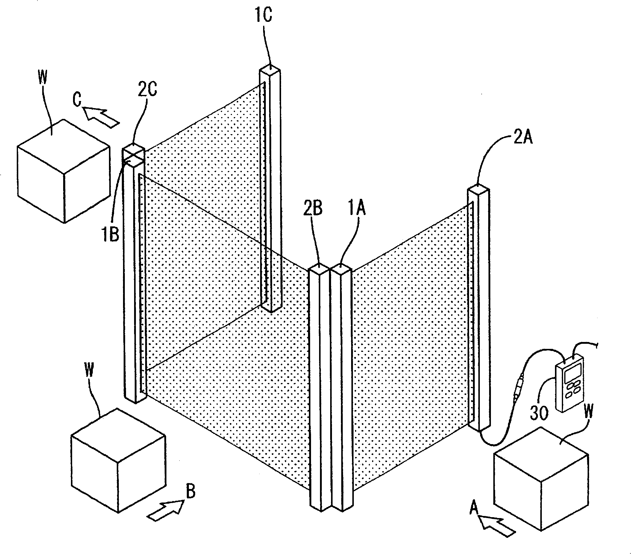
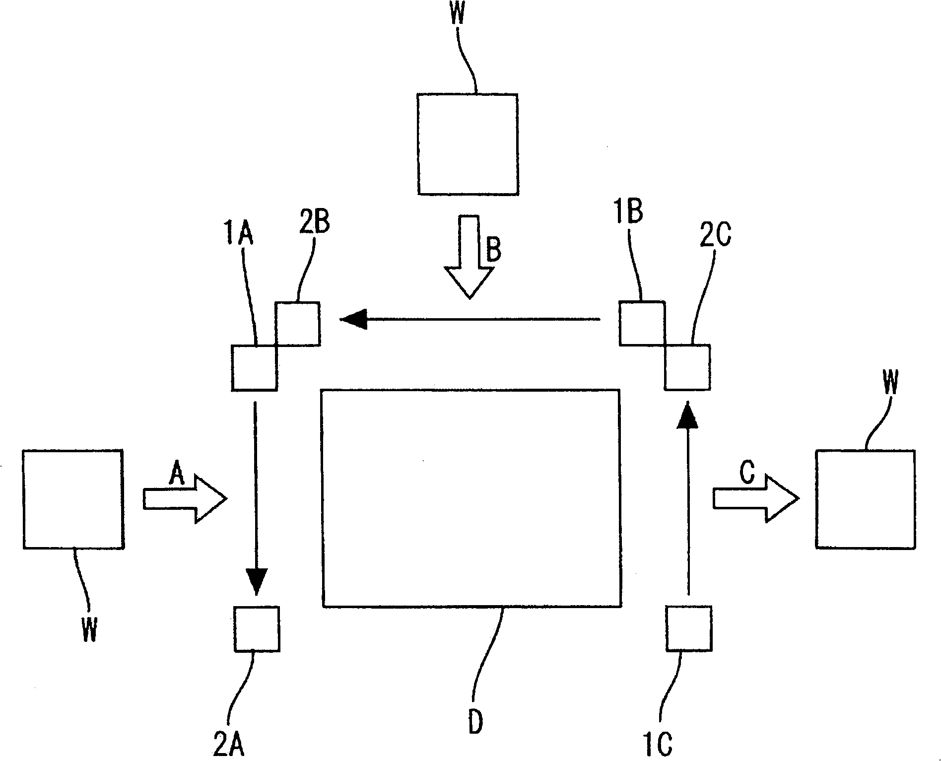
[0020] Combine below Figures 1 to 4 , Embodiment 1 of the multi-optical axis photoelectric sensor of the present invention will be described. Such as figure 1 and figure 2 As shown, the multi-optical axis photoelectric sensor of this embodiment is installed near the press installed in the production line at the boundary between the dangerous area D where workers are prohibited from entering and the safe area where workers are allowed to enter.

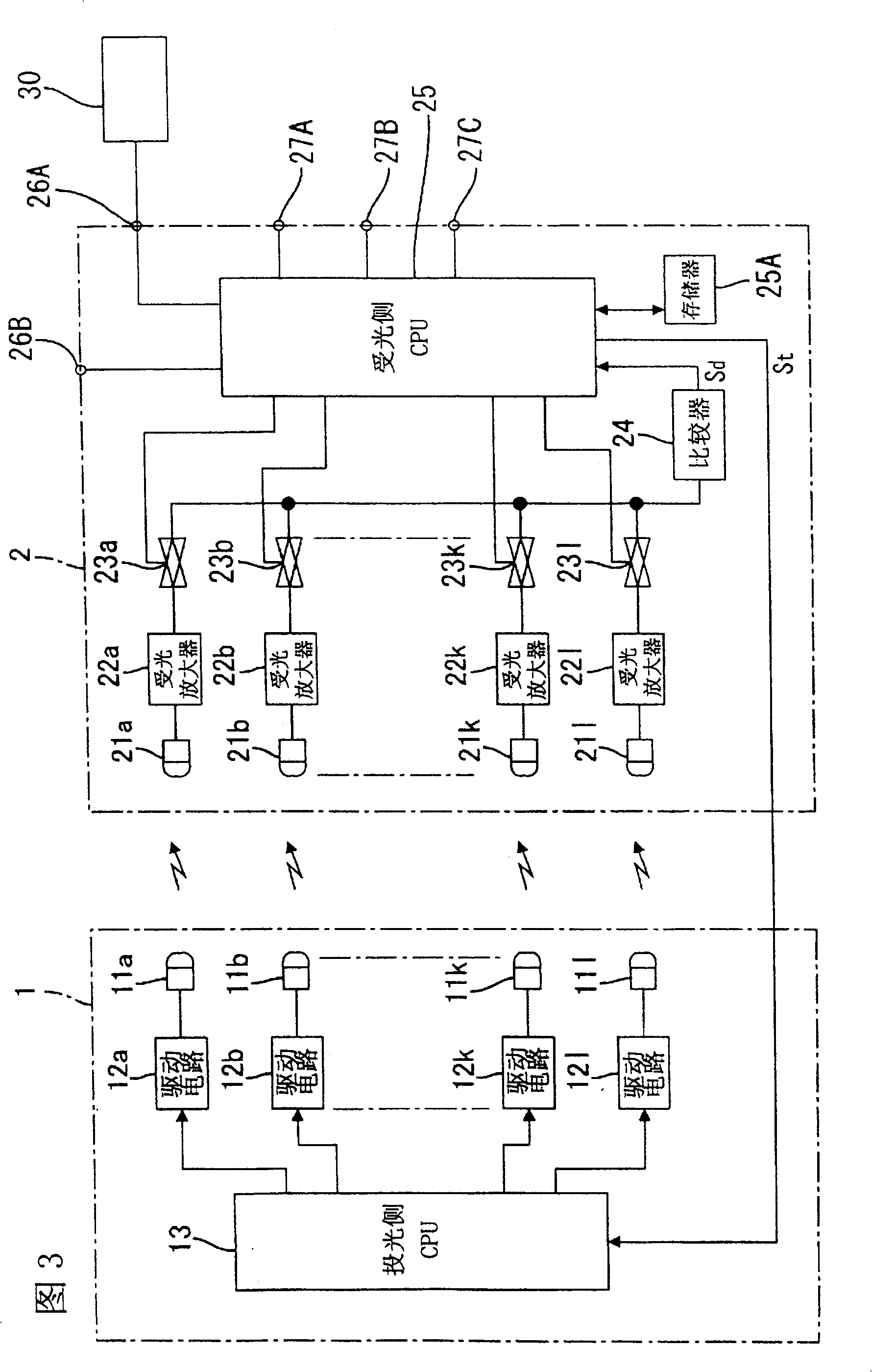
[0021] This multi-optical axis photoelectric sensor is configured in a state where a light projector 1 (light projecting unit) and a light receiver 2 (light receiving unit) face each other, and has, for example, 12 channels of optical axes. On the surface of the light projector 1 facing the light receiver 2, one (total 12) light projecting elements 11a to 11l arranged on each channel are arranged in a row in the vertical direction, and on the surface of the light receiver 2 facing the light projector 1 On the top, the light receiv...

Embodiment 2

[0040] Refer below Figure 5 The second embodiment of the present invention is described, and the same parts as the first embodiment are marked with the same symbols to omit repeated descriptions, and the descriptions on the same functions and effects are also omitted.

[0041] In this embodiment, the transmissive photoelectric sensors 4A, 4B (corresponding to "external equipment", "external sensors") that detect the shading caused by the workpiece W are installed in front of the light receivers 2A and 2B (opposite to the danger zone D). The safe area side), the signal output lines of these photoelectric sensors 4 are connected to the input ports 27 of the respective photoreceivers 2A, 2B. In addition, when the light receivers 2A and 2B receive the detection signals from the corresponding photosensors 4A, 4B, the light receiving signals from the light receiving elements 11a to 11l constituting the channels stored in the memory 25A are invalidated for a predetermined time, and ...

Embodiment 3

[0047] Refer below Figure 6 to Figure 9 Embodiment 3 of the present invention is described, and the parts identical to those in Embodiment 1 are marked with the same symbols to omit repeated descriptions, and descriptions on the same functions and effects are also omitted.

[0048] In this embodiment, the workpieces W flow through the conveying lines (not shown in the figure) vertically stacked in three layers, and the corresponding workpieces W are sent into the dangerous area D respectively. The light projector 1 and the light receiver 2 are arranged in a group on both sides of the conveying line, and three sets of photosensors 4A to 4C are arranged at predetermined intervals in the longitudinal direction in front of it (on the side of the safe area opposite to the dangerous area D). The optical axis of the photoelectric sensor 4A on the top layer is located between the second and third channels of the light emitter 1 and the light receiver 2, the optical axis of the photoe...


PUM


Abstract

PROBLEM TO BE SOLVED: To provide a multiple beam axis photoelectric sensor which can override the beam receiving signal from an optional beam receiving element for a predetermined time. SOLUTION: The multiple beam axis photoelectric sensor is provided with a beam emitter 1 equipped with two or more beam emitting elements 11a-11l and with a beam receiver 2 equipped with two and more beam receiving elements 21a-21l each of which constitutes a channel respectively in a pair with its counterpart in beam emitting elements 11a-11l, performing detection operation one by one for each channel based on whether or not the beam from each of emitting element 11a-11l is received by each of receiving element 21a-21l in the same channel. Optional channels among the two or more channels are designated by an external console 30 and also the designation is memorized to a memory 25A, therefore, a CPU 25 on the beam receiving side overrides, for only a predetermined period, beam receiving signals of the receiving elements 21a-21l consisting of the channels designated by the external console, based on the control signal which is input from an external control circuit through an input port 27. COPYRIGHT: (C)2004,JPO&NCIPI

Description

technical field [0001] The invention relates to a multi-optical axis photoelectric sensor with multiple channels formed by multiple light emitting and receiving mechanisms. Background technique [0002] A multi-optical axis photoelectric sensor is arranged, for example, around a press installed in a production line at the boundary between a dangerous area where workers are prohibited from entering and a safe area where workers are allowed to enter. In this multi-optical axis photoelectric sensor, a light projector having a plurality of light projecting elements and a light receiver having a plurality of light receiving elements corresponding to each light projecting element are arranged oppositely, whereby a channel is formed by corresponding light projecting elements and light receiving elements. . The light-emitting elements installed in the light-emitting device perform light-emitting operations sequentially according to the predetermined light-emitting timing, and detec...

Claims


Application Information

Patent Timeline
Patent Type & Authority Patents(China)
IPC IPC(8): G08B13/183G01V8/20F16P3/14B23Q11/00B30B15/00H01H35/00
Inventor 和气徹渡边义幸加知辉郎
Owner PANASONIC INDAL DEVICES SUNX
Why Eureka
Try Eureka