Plasma display panel

A display panel, plasma technology, applied in hats, electronic timers, clocks and other directions, can solve problems such as panel breakage

Inactive Publication Date: 2009-01-07
SAMSUNG SDI CO LTD
View PDF3 Cites 0 Cited by
  • Summary
  • Abstract
  • Description
  • Claims
  • Application Information

AI Technical Summary

Problems solved by technology

Therefore, the temperature difference between the display area and the non-display area reaches 60°C, which can directly lead to panel breakage

Method used


Image

  • Plasma display panel
  • Plasma display panel
  • Plasma display panel

Examples


Embodiment Construction

[0040] The present invention will be described in more detail below in conjunction with the relevant drawings, in which specific exemplary embodiments of the present invention are shown.

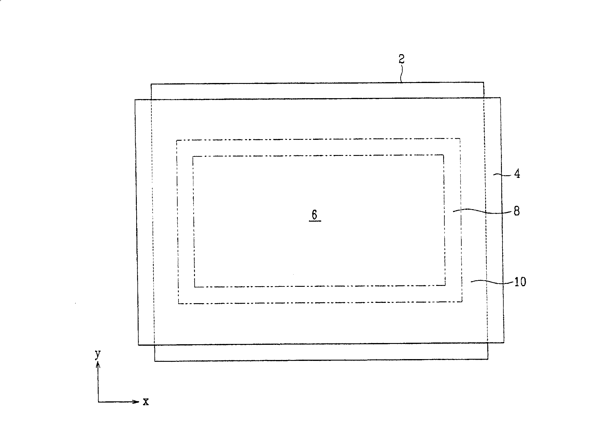
[0041] figure 1 It is a schematic plan view of a PDP that can be used to implement an exemplary embodiment of the present invention. Refer here figure 1 Describing the first to fifth exemplary embodiments, those skilled in the art can understand that any one of the first to fifth exemplary embodiments can be used in figure 1 In the PDP, but not limited to this.

[0042] Such as figure 1 As shown in, the first substrate 2 (hereinafter referred to as the "rear substrate") and the second substrate 4 (hereinafter referred to as the "front substrate") are substantially parallel to each other with a predetermined distance or gap provided therebetween, and are assembled to each other Constitute the outline of the PDP. A display area 6, a middle area 8 and a non-display area 10 are divided on the re...


PUM


Abstract

The present invention discloses a plasma display panel capable of reducing or preventing panel breakage and aging failure during the aging process for discharge stabilization. The plasma display panel includes first and second substrates facing each other and having a display region at a center of the substrates, a non-display region formed around a periphery of the display region, and an intermediate region disposed between the display region and the non-display region. Address electrodes are formed on the first substrate and extend parallel to each other. Barrier ribs are arranged at the display region and the intermediate region. The barrier ribs define discharge cells between the substrates. Display electrodes are formed on the second substrate in a direction crossing the address electrodes. An area ratio of the display electrodes to corresponding discharge cells in the intermediate region is smaller than the area ratio thereof in the display region.

Description

Technical field [0001] The present invention relates to a plasma display panel, and in particular to a plasma display panel that prevents panel damage and aging failure during aging treatment for discharge stability. Background technique [0002] Generally, a plasma display panel (hereinafter referred to as "PDP") is a display device that excites phosphors by ultraviolet rays generated by gas discharge in discharge cells to display images. Because the PDP can constitute a high-resolution, wide-screen display device, it has received special attention as a thin and light display device in the future. [0003] PDP generally has a triode surface discharge structure. The triode surface discharge PDP includes a first substrate with address electrodes, and a second substrate spaced apart from the first substrate and provided with two electrodes arranged on the same plane. The barrier ribs are arranged between the two substrates to separate a plurality of discharge cells. [0004] The di...

Claims


Application Information

Patent Timeline
Patent Type & Authority Patents(China)
IPC IPC(8): H01J17/49H01J11/24
CPCA42B1/004A42B1/24A44B17/00A44B18/00A44D2203/00G04G21/025
Inventor 权宰翊姜景斗
Owner SAMSUNG SDI CO LTD
Why Eureka
Try Eureka