Air-cooled coil unit of a linear motor

A linear motor, coil unit technology, applied in electrical components, electrical components, cooling/ventilation devices, etc., can solve the problem of loss of magnetic flux in cooling channels, and achieve the effect of high power density

Inactive Publication Date: 2009-01-14
ASM ASSEMBLY SYST GMBH & CO
View PDF9 Cites 1 Cited by
  • Summary
  • Abstract
  • Description
  • Claims
  • Application Information

AI Technical Summary

Problems solved by technology

Such a pipe connection is not suitable for fast-moving coil components, for example, which accommodate electrical components for the purpose of providing substrates
In addition the cooling channels lose the magnetic flux

Method used


Image

  • Air-cooled coil unit of a linear motor
  • Air-cooled coil unit of a linear motor
  • Air-cooled coil unit of a linear motor

Examples


Embodiment Construction

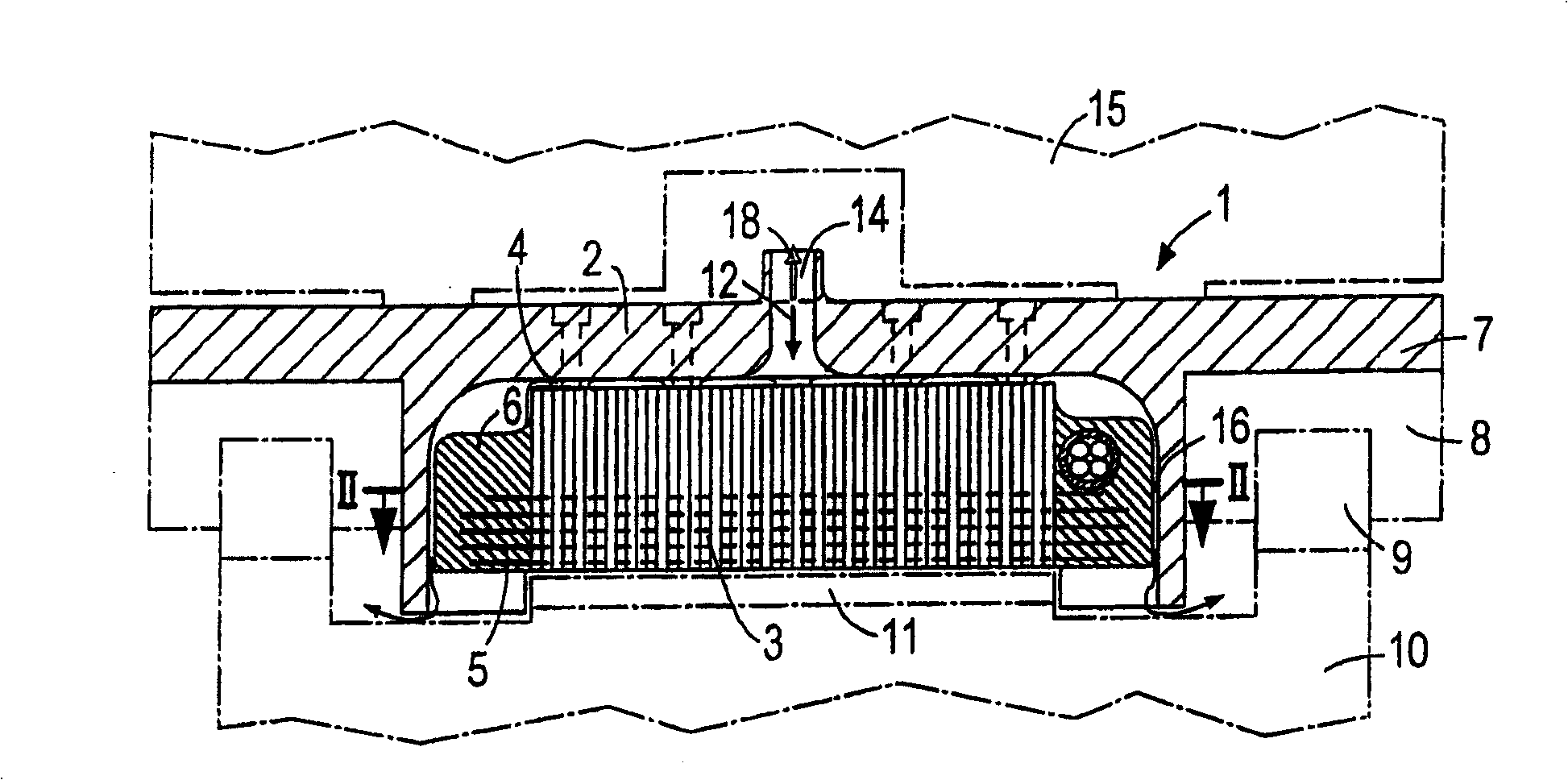
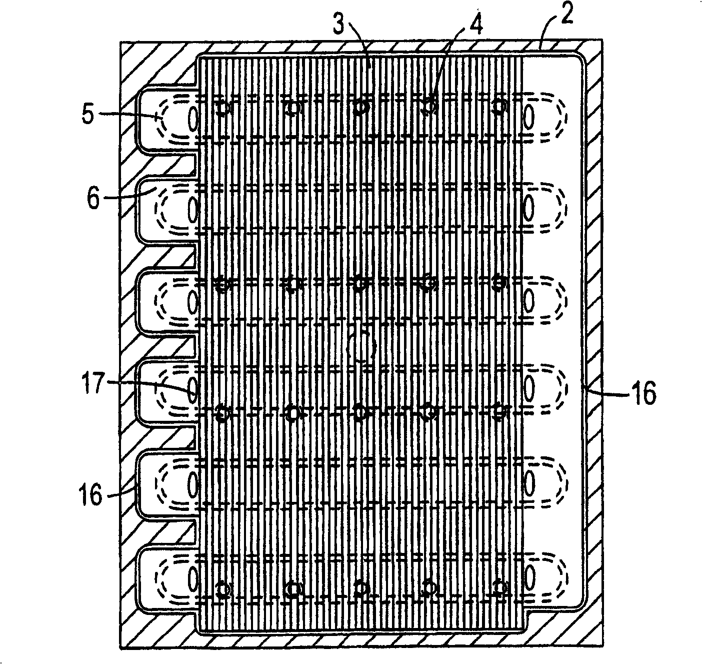
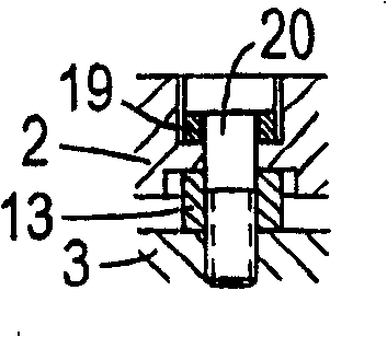
[0021] according to figure 1 and 2 A coil unit 1 has a housing 2 on which a core 3 made of laminations is fastened via a support element 4 which is designed as a support projection integrally formed on the housing 2 . The iron core 3 is fixedly connected to the winding of the electrical coil 5 via a casting compound 6 . The housing 2 has a laterally protruding flange-shaped projection 7 for fastening a linear guide element 8 . This guide element cooperates with a corresponding guide rail 9 of a fixed guide rail 10 . Between the guide rails 9, the guide rail 10 has a magnetic rail 11 made of permanent magnets arranged next to each other in the direction of movement.

[0022] The housing 2 is open on the side facing the magnetic track 11 and surrounds the core 3 with the coil 5 at a narrow distance on the other side. This distance serves as a surrounding slot 16 whose width is reduced to a fraction of a half millimeter. The core 3 and the coil 5 together with the potting co...


PUM


Abstract

A coil unit (1) of a single-sided linear motor has an iron core (3) with a coil (5), which is connected to the iron core (3) via a casting compound (6) to form a molded part. The molded part is surrounded by a housing (2), wherein a narrow gap (16) is formed between the housing and the molded part, through which cooling air can blow through. As a result, the core (3) with the coil (5) is cooled over a large area and the housing (2) is thermally insulated from the core (3) and the coil (5).

Description

technical field [0001] The invention relates to a coil unit of a linear motor, the coil unit having an electromagnetic coil, at least one core, a housing surrounding the coil and the core, the housing being open towards a magnetic track of the linear motor, wherein the core is fixedly connected to the housing, In this case, the coil is fixed by a potting compound, while at least one cooling air duct is provided inside the housing. Background technique [0002] Such a coil unit is known, for example, from DE 19842384 A1. Behind it, an electric motor primary component is accommodated in a housing known as a trolley and can be moved on a rail-shaped secondary component of the guide housing. Such a primary component is generally produced from a magnetic core, which can be actuated by means of transverse coils. Usually this coil is cast and fixed with the core and casing. Ventilation slots are formed in the housing according to slots 3 , rows 23 to 26 , which dissipate the hea...

Claims


Application Information

Patent Timeline
Patent Type & Authority Patents(China)
IPC IPC(8): H02K41/02H02K41/03H02K9/04
CPCH02K41/031H02K9/04H02K41/02
Inventor W·安德施
Owner ASM ASSEMBLY SYST GMBH & CO
Why Eureka
Try Eureka