Side-lighting type back light module

A backlight module, light incident surface technology, applied in optics, nonlinear optics, instruments, etc., to achieve the effect of improved conduction

Active Publication Date: 2009-01-21
AU OPTRONICS CORP
View PDF8 Cites 1 Cited by
  • Summary
  • Abstract
  • Description
  • Claims
  • Application Information

AI Technical Summary

Problems solved by technology

[0010] One of the purposes of the present invention is to improve the heat accumulation problem of the existing side-lit type backlight module

Method used


Image

  • Side-lighting type back light module
  • Side-lighting type back light module
  • Side-lighting type back light module

Examples


Embodiment Construction

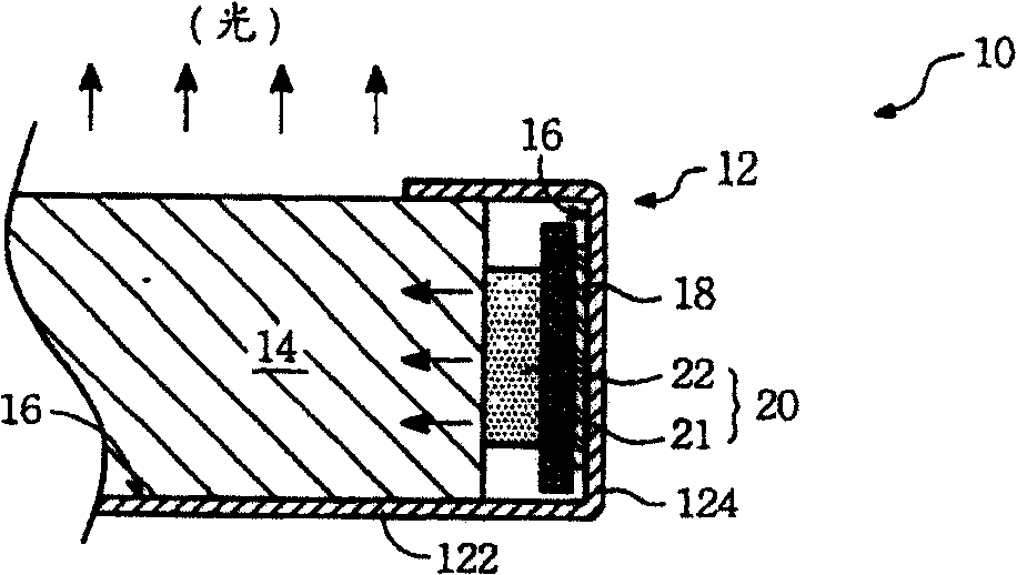
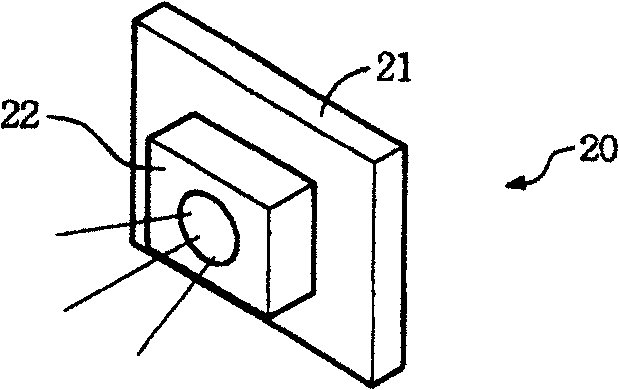
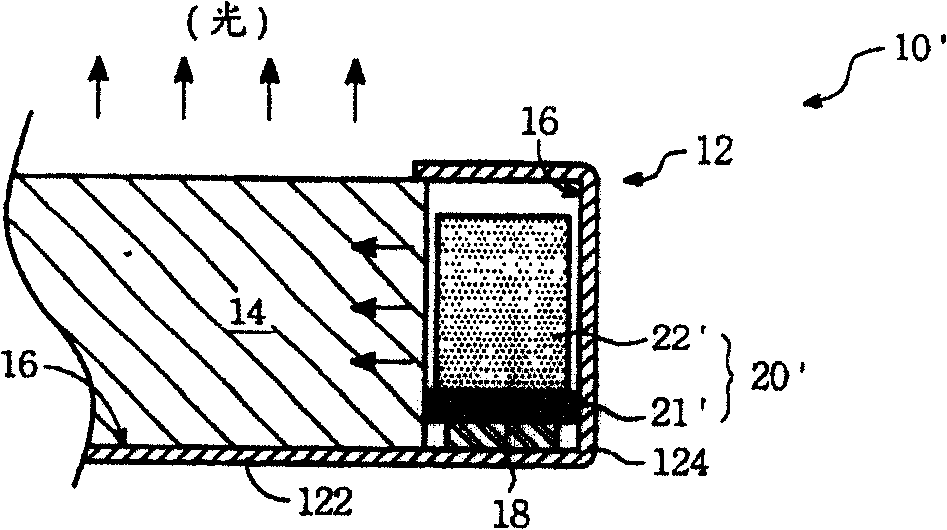
[0062] Please refer to Figure 3A and Figure 3B , is a side cross-sectional schematic diagram of a side-light incident type backlight module of the present invention. The backlight module 30 includes a substrate 321 , a light guide plate 34 , a light emitting diode 42 and a metal sheet 45 . Figure 3A It shows the situation that the light emitting diode 42 is not combined in front of the backlight module 30; Figure 3B A situation where the light emitting diode 42 has been combined in the backlight module 30 is shown.

[0063] Wherein, the substrate 321 has a first surface 321a, a second surface 321b and a hole 321c. The hole 321c passes through the first surface 321a and the second surface 321b. The substrate 321 is part of a back bezel 32 , and the base 32 further includes an extension portion 323 extending from the periphery of the substrate 321 .

[0064] The light guide plate 34 is disposed on the first surface 321a and does not cover the hole 321c. The light guide...


PUM

PropertyMeasurementUnit
Angleaaaaaaaaaa

Abstract

Disclosed is a background module which has light injected from side. The module comprises a base board, a light conducting board, a light emitting diode and a metal slice. The base board includes a first plane, a second plane and a hole which goes through the first and the second planes. The light conducting board with a light-injecting plane is installed on the first plane and doesn't cover the hole. The light emitting diode goes through the hole and is combined with the base board. The metal slice and the light-injecting plane of the light conducting board form a space for covering the light emitting diode in it.

Description

technical field [0001] The present invention relates to an edge-type backlight module, in particular to an edge-type backlight module using a light emitting diode (Light Emitting Diode, LED) as a light source. Background technique [0002] Please refer to Figure 1A and Figure 1B , Figure 1A It is a side cross-sectional schematic diagram of an existing side-light type backlight module; Figure 1B show Figure 1A The light source group in . The backlight module 10 includes a base (back bezel) 12 , a light guide plate 14 , multilayer optical films (not shown), a reflector 16 and a light source group 20 . The light source group 20 includes a circuit board 21 and a light emitting diode (LED) 22 . The function of the backlight module 10 is to provide a uniform surface light source to a display panel, such as a liquid crystal panel. [0003] In the backlight module 10 , the base 12 has a base plate 122 and has an extension portion 124 extending from the peripheral portion of...

Claims


Application Information

Patent Timeline
IPC IPC(8): G02F1/1335H01L33/00G09F9/00
Inventor 郭汉斌陈丽惠
Owner AU OPTRONICS CORP
Why Eureka
Try Eureka