Circulating fluidized bed boiler capable of adjusting circulating ash flow

A technology of circulating fluidized bed and circulating ash, which is used in fluidized bed combustion equipment, fuel burning in a molten state, lighting and heating equipment, etc., can solve problems such as small load adjustment range, low ash content, and boiler inner wall wear Achieve the effect of improving ash adjustment capacity, convenient load adjustment and reducing boiler load

Active Publication Date: 2015-10-21
HMEI THREAD CO LTD OF YINBIN SICHUAN
View PDF6 Cites 5 Cited by
  • Summary
  • Abstract
  • Description
  • Claims
  • Application Information

AI Technical Summary

Problems solved by technology

The load of the boiler needs to be adjusted and changed depending on the situation. The existing technology can only rely on the input of wind and coal to adjust the boiler load. This traditional adjustment method has two defects: one is slow speed; the other is load adjustment. The range is small, only 65%-105%
However, when the load adjustment of the boiler is completed, two problems are brought about during stable operation: one is that at low load, the amount of ash in the furnace is too much compared to the low load, the bed temperature is low, and the combustion efficiency is low , large wear; second, when the load is high, the amount of ash in the furnace is relatively small relative to the load, and the bed tempera

Method used


Image

  • Circulating fluidized bed boiler capable of adjusting circulating ash flow
  • Circulating fluidized bed boiler capable of adjusting circulating ash flow
  • Circulating fluidized bed boiler capable of adjusting circulating ash flow

Examples


Embodiment 1

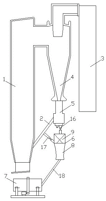
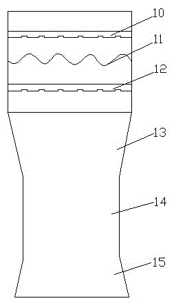
[0037] see figure 1 and figure 2 , a circulating fluidized bed boiler that can adjust the circulating ash flow, including a furnace 1, an ash return pipe 2, a tail flue 3, a cyclone separator 4 arranged between the furnace 1 and the tail flue 3, and a cyclone separator connected to the The ash return device 5 at the bottom of the furnace 4 and the cyclone separator 4 are connected to the furnace 1 and the tail flue 3 respectively, and the ash return device 5 is connected to the bottom of the furnace 1 through the ash return pipe 2, and also includes an ash adjustment device 6 and a slag cooler 7 , the ash adjuster 6 is composed of the lower Venturi fluidization air chamber 8 and the upper cylindrical cold ash chamber 9, the Venturi fluidization air chamber 8 and the cold ash chamber 9 are connected, and the cold ash chamber 9 is From top to bottom, the first flow sharing ring plate 10, the serpentine cooling coil 11 and the second flow sharing ring plate 12 are sequentially ...

Embodiment 2

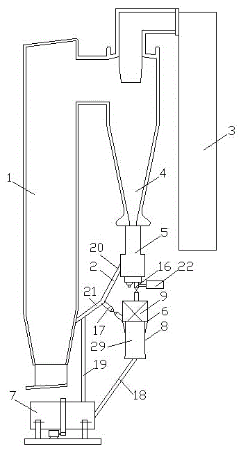
[0040] see figure 2 and image 3 , a circulating fluidized bed boiler that can adjust the circulating ash flow, including a furnace 1, an ash return pipe 2, a tail flue 3, a cyclone separator 4 arranged between the furnace 1 and the tail flue 3, and a cyclone separator connected to the The ash return device 5 at the bottom of the furnace 4 and the cyclone separator 4 are connected to the furnace 1 and the tail flue 3 respectively, and the ash return device 5 is connected to the bottom of the furnace 1 through the ash return pipe 2, and also includes an ash adjustment device 6 and a slag cooler 7 , the ash adjuster 6 is composed of the lower Venturi fluidization air chamber 8 and the upper cylindrical cold ash chamber 9, the Venturi fluidization air chamber 8 and the cold ash chamber 9 are connected, and the cold ash chamber 9 is From top to bottom, the first flow sharing ring plate 10, the serpentine cooling coil 11 and the second flow sharing ring plate 12 are sequentially ...

Embodiment 3

[0045] see figure 2 and image 3 , a circulating fluidized bed boiler that can adjust the circulating ash flow, including a furnace 1, an ash return pipe 2, a tail flue 3, a cyclone separator 4 arranged between the furnace 1 and the tail flue 3, and a cyclone separator connected to the The ash return device 5 at the bottom of the furnace 4 and the cyclone separator 4 are connected to the furnace 1 and the tail flue 3 respectively, and the ash return device 5 is connected to the bottom of the furnace 1 through the ash return pipe 2, and also includes an ash adjustment device 6 and a slag cooler 7 , the ash adjuster 6 is composed of the lower Venturi fluidization air chamber 8 and the upper cylindrical cold ash chamber 9, the Venturi fluidization air chamber 8 and the cold ash chamber 9 are connected, and the cold ash chamber 9 is From top to bottom, the first flow sharing ring plate 10, the serpentine cooling coil 11 and the second flow sharing ring plate 12 are sequentially ...


PUM


Abstract

The invention discloses a circulating fluidized bed boiler capable of adjusting a circulating ash flow. The circulating fluidized bed boiler comprises a hearth, an ash return pipe, a tail flue, a cyclone separator and an ash returner, and is characterized by further comprising an ash conditioner and a slag cooler, wherein the ash conditioner consists of a venturi fluidized air chamber and a cylindrical ash cooling chamber; the venturi fluidized air chamber is communicated with the ash cooling chamber; a first flow equalizing annular plate, a snakelike cooling coil and a second flow equalizing annular plate are connected into the ash cooling chamber; the first flow equalizing annular plate and the second flow equalizing annular plate are both porous structures; the venturi fluidized air chamber is formed by an expansion section, a cylinder section and a shrinkage section, which are communicated with each other; the ash cooling chamber is connected with an ash return valve of the ash returner through an ash discharge pipe; an ash return pipe is connected between the ash return pipe and the ash cooling chamber; an isolating valve is mounted on the ash return pipe; and the venturi fluidized air chamber is connected with the slag cooler through the ash discharge pipe. The circulating fluidized bed boiler is advantageous in that, circulating ash can be introduced to the boiler to adjust the load inside in a large range, so that the combustion efficiency of a fuel in the boiler is greatly improved, and the inner wall wear of the boiler is reduced.

Description

technical field [0001] The invention relates to the technical field of circulating fluidized bed boilers, in particular to a circulating fluidized bed boiler capable of adjusting circulating ash flow. Background technique [0002] The early circulating fluidized bed boiler had a relatively high fluidization velocity, so it was called a fast circulating fluidized bed boiler. The basic theory of fast circulating bed boiler can also be used in circulating fluidized bed boiler. The circulating fluidized bed boiler adopts a single drum and natural circulation mode, and is generally divided into two shafts at the front and the rear. The front shaft is a general suspension structure, surrounded by membrane water cooling walls. From bottom to top, it is the primary air chamber, dense phase area, and dilute phase area, and the tail flue is from top to bottom: high temperature superheater, low temperature superheater, economizer, and air preheater. The tail shaft adopts a supportin...

Claims


Application Information

Patent Timeline
IPC IPC(8): F23C10/10F23C10/18F23C10/32
CPCF23C10/10F23C10/18F23C10/32F23C2206/10
Inventor 肖雪峰蒋文斌冯静张西平
Owner HMEI THREAD CO LTD OF YINBIN SICHUAN
Why Eureka
Try Eureka