Compressor jet flow path structure

A technology of compressors and centrifugal compressors, applied in mechanical equipment, radial flow pumps, machines/engines, etc., can solve problems such as increased material costs, poor controllability of refrigerant mixing, and decreased rigidity of rotating shafts. cost, improve compression efficiency, and reduce interference

Active Publication Date: 2009-01-28
IND TECH RES INST
View PDF5 Cites 0 Cited by
  • Summary
  • Abstract
  • Description
  • Claims
  • Application Information

AI Technical Summary

Problems solved by technology

[0006] However, this existing two-stage (or multi-stage) compression design has its disadvantages in efficiency and cost. This is due to the fact that in the two-stage compression, injection into the compressor flow channel from the R2 direction (via the jet channel outlet 111) If the refrigerant cannot be evenly mixed with the refrigerant in the mainstream field at the outlet of the return guide vane 14, the pressure, temperature and density distribution of the fluid in each section will be uneven, which will affect the angle at which the refrigerant enters the next-stage impeller, forming an incident Angle (Incidence Angle) difference, resulting in reduction of aerodynamic efficiency (Aerodynamic Efficiency)
[0007] Therefore, for the existing compressor jet channel structure that adopts single-side jet flow, since the single-side jet flow interferes greatly with the velocity field of the main refrigerant flow channel, in order to make the refrigerant evenly mixed and avoid the above problems, usually Consider lengthening the flow channel between the two-stage impellers, thereby lengthening the axial cantilever length L1 of the cantilever rotating shaft; this will result in a decrease in the rigidity of the rotating shaft, and at the same time increase the flow loss due to the lengthening of the flow channel and the axial dimension of the compressor Larger, there will be a great loss in efficiency, and the cost of materials will increase, and the control of refrigerant mixing will be poor
[0008] These are serious problems derived from one-sided jet flow, forming a bottleneck in the operation design of multi-stage centrifugal compressors

Method used


Image

  • Compressor jet flow path structure
  • Compressor jet flow path structure
  • Compressor jet flow path structure

Examples


Embodiment

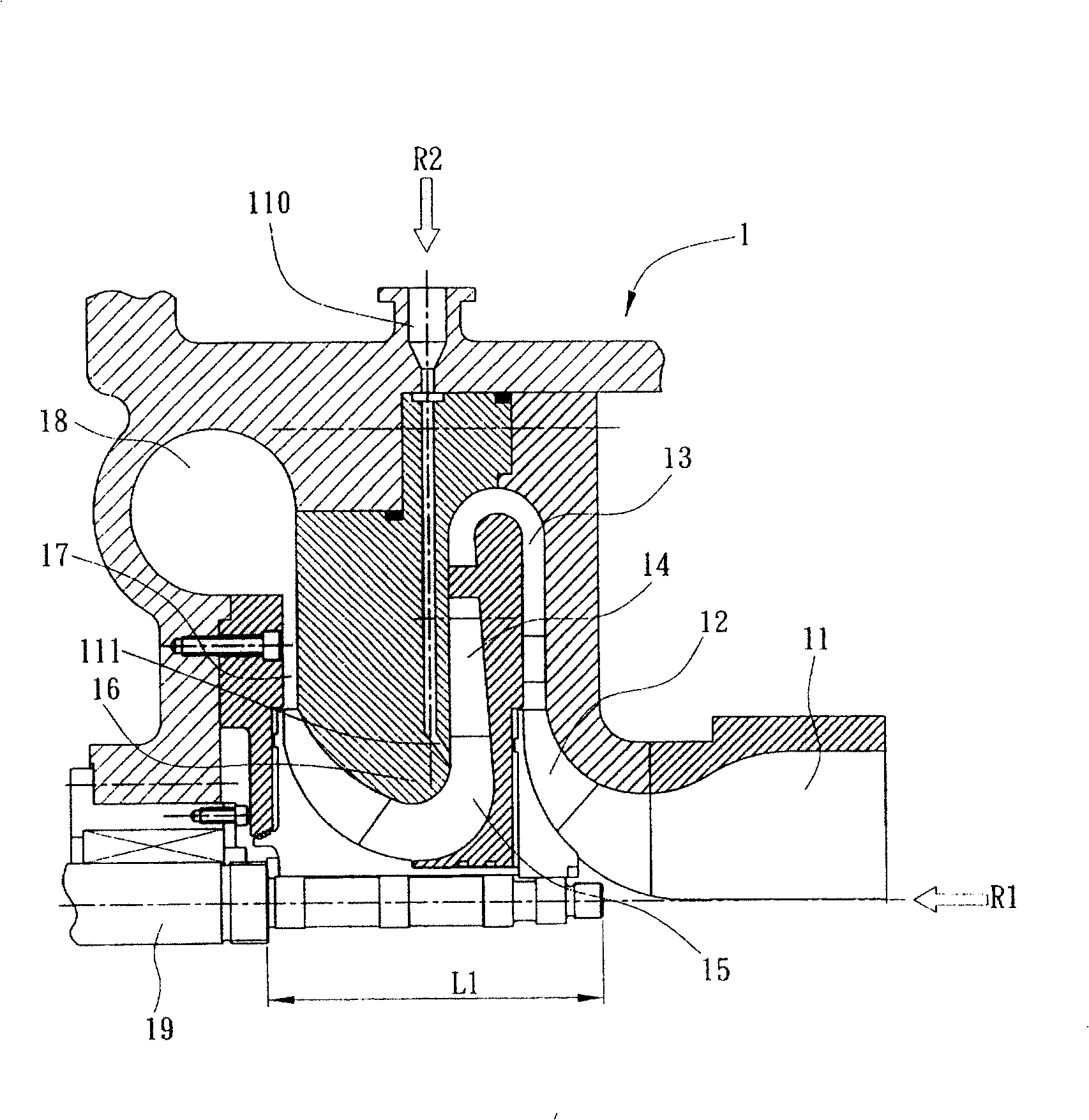
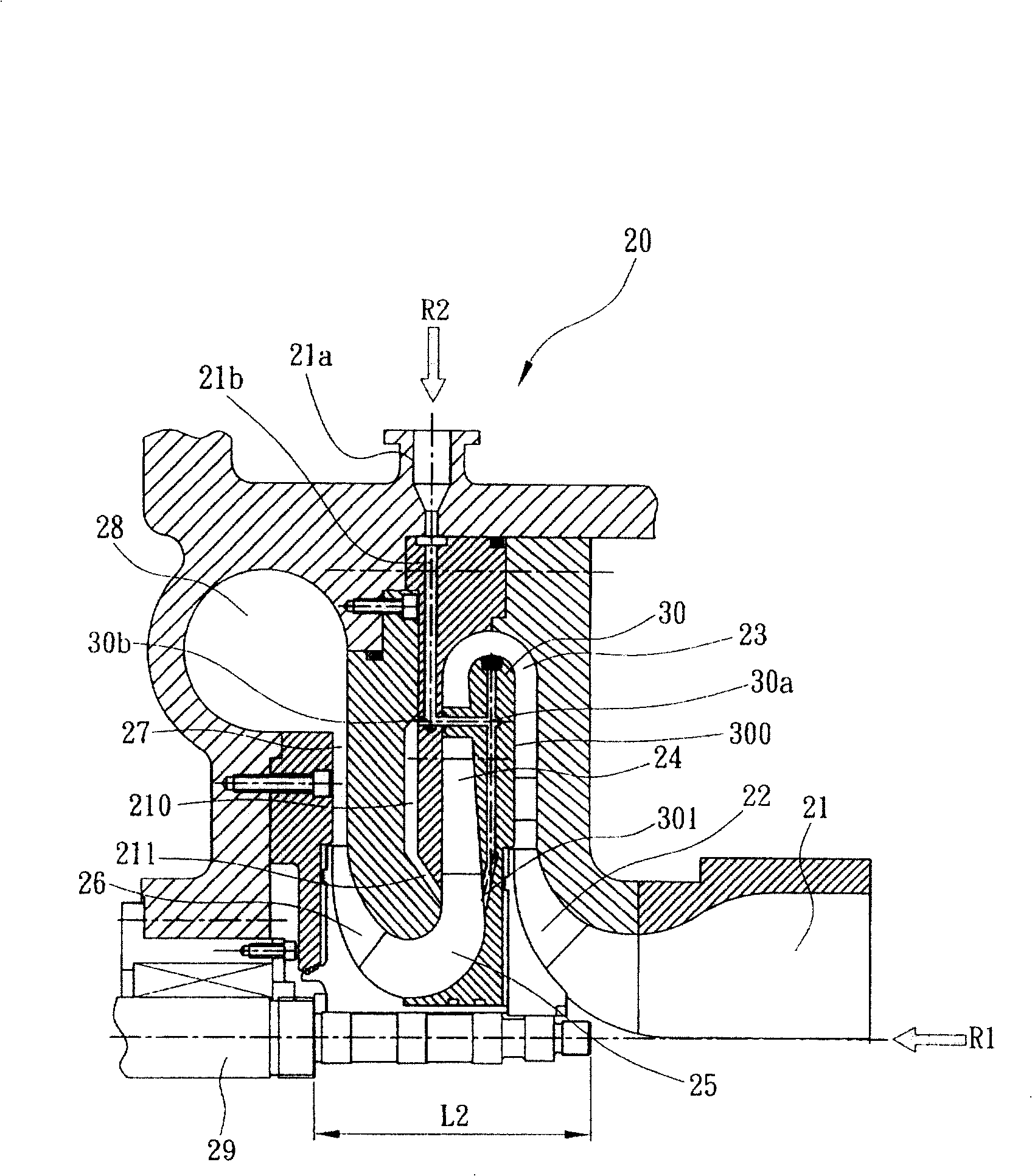
[0025] The compressor spray channel structure proposed by the present invention is arranged in a multi-stage centrifugal compressor, such as figure 2 In the shown embodiment, the multi-stage centrifugal compressor 20 is an example of a two-stage centrifugal compressor, which includes a compressor inlet 21, a first-stage centrifugal compression impeller 22, a first Compression / diffuser flow elements such as stage diffuser flow channel 23, return guide vane 24, return flow bend 25, second stage centrifugal compression impeller 26, second stage diffuser flow channel 27, volute 28, and an axial The rotating shaft 29 with a cantilever extension length of L2 (L2

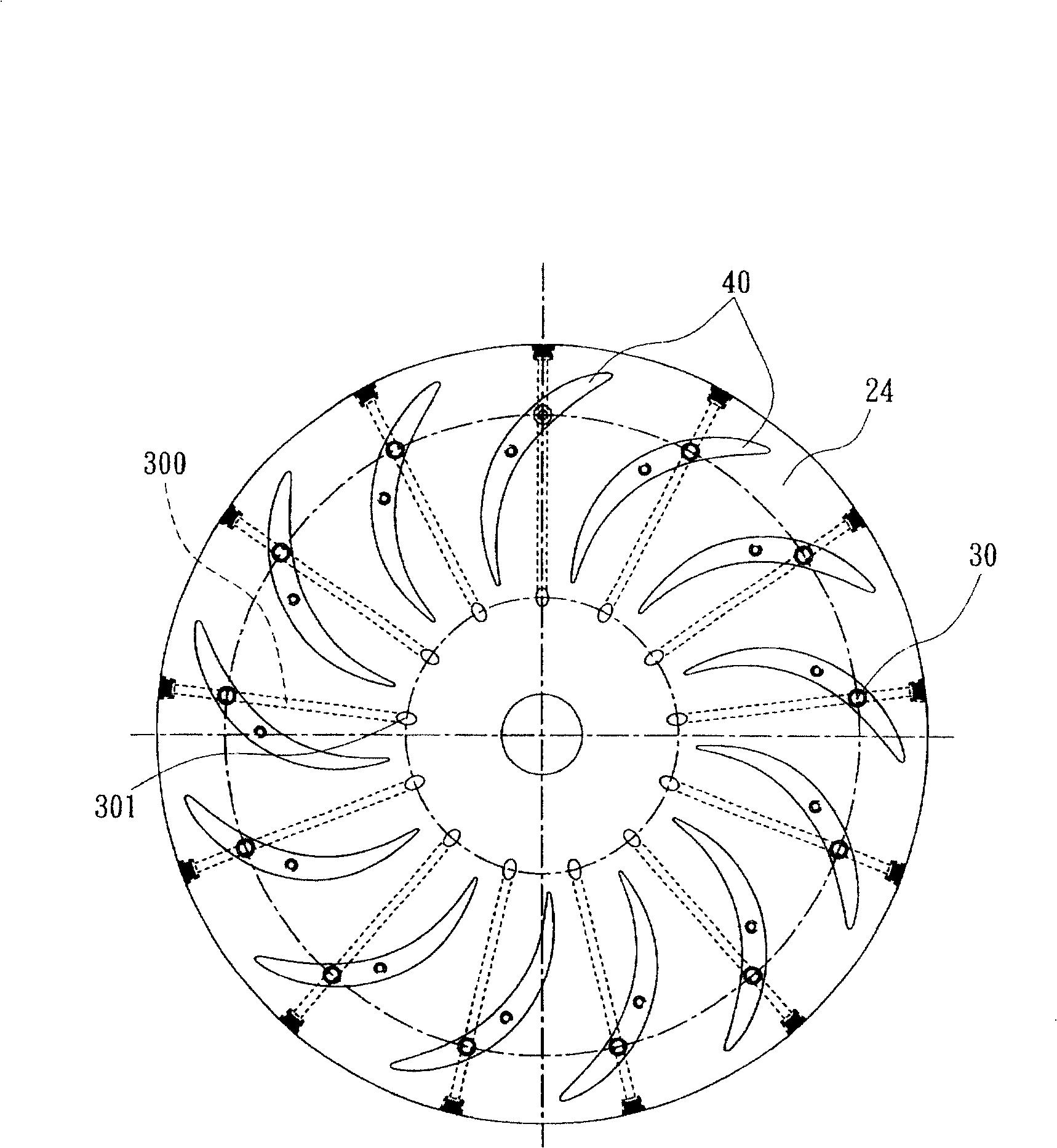
[0026] At the same time, the compressor spray channel structure of the present invention is a double-sided spray chan...


PUM


Abstract

A spray channel structure for the multi-class centrifugal compressor with curved reflux channel and reflux guide blade is composed of a bidirectional flow channel for the bidirectional division of the refrigerant filled externally and with the first and the second outlets, the first lateral spray channel communicated with the first outlet, and the second lateral spray channel communicated with the second outlet. Its advantages are uniform mixing of refrigerant and short channel and rotary axle.

Description

technical field [0001] The invention relates to a compressor spray channel structure, in particular to a compressor spray channel structure used in the double-side injection of refrigerant in the middle-pressure section of a multi-stage centrifugal compressor. Background technique [0002] For refrigeration machinery such as centrifugal refrigerators, centrifugal compressors are currently used as tools for pressurized delivery of refrigerants, and in order to improve the refrigeration cycle performance and refrigeration capacity of the refrigerator system, two or more The multi-stage (Multi-Stage) compressor with two or more stages replaces the traditional single-stage (Single-Stage) compressor, thereby improving the energy utilization efficiency of the refrigerator. [0003] The reason is that the multi-stage compression process is an Economizer Cycle process, through the function of the economizer in the middle of each stage, most of the refrigerant enthalpy (Enthalpy) can...

Claims


Application Information

Patent Timeline
Patent Type & Authority Patents(China)
IPC IPC(8): F04D29/44F04D17/10
Inventor 陈景富强忠萍周永乐严正忠
Owner IND TECH RES INST
Why Eureka
Try Eureka