A surgical rotary bit of binding instruments
A technology of rotating cutter head and binding instrument is applied in the field of medical equipment to achieve the effects of reducing binding force, reducing resistance and reducing side effects
- Summary
- Abstract
- Description
- Claims
- Application Information
AI Technical Summary
Problems solved by technology
Method used
Image
Examples
Embodiment 1
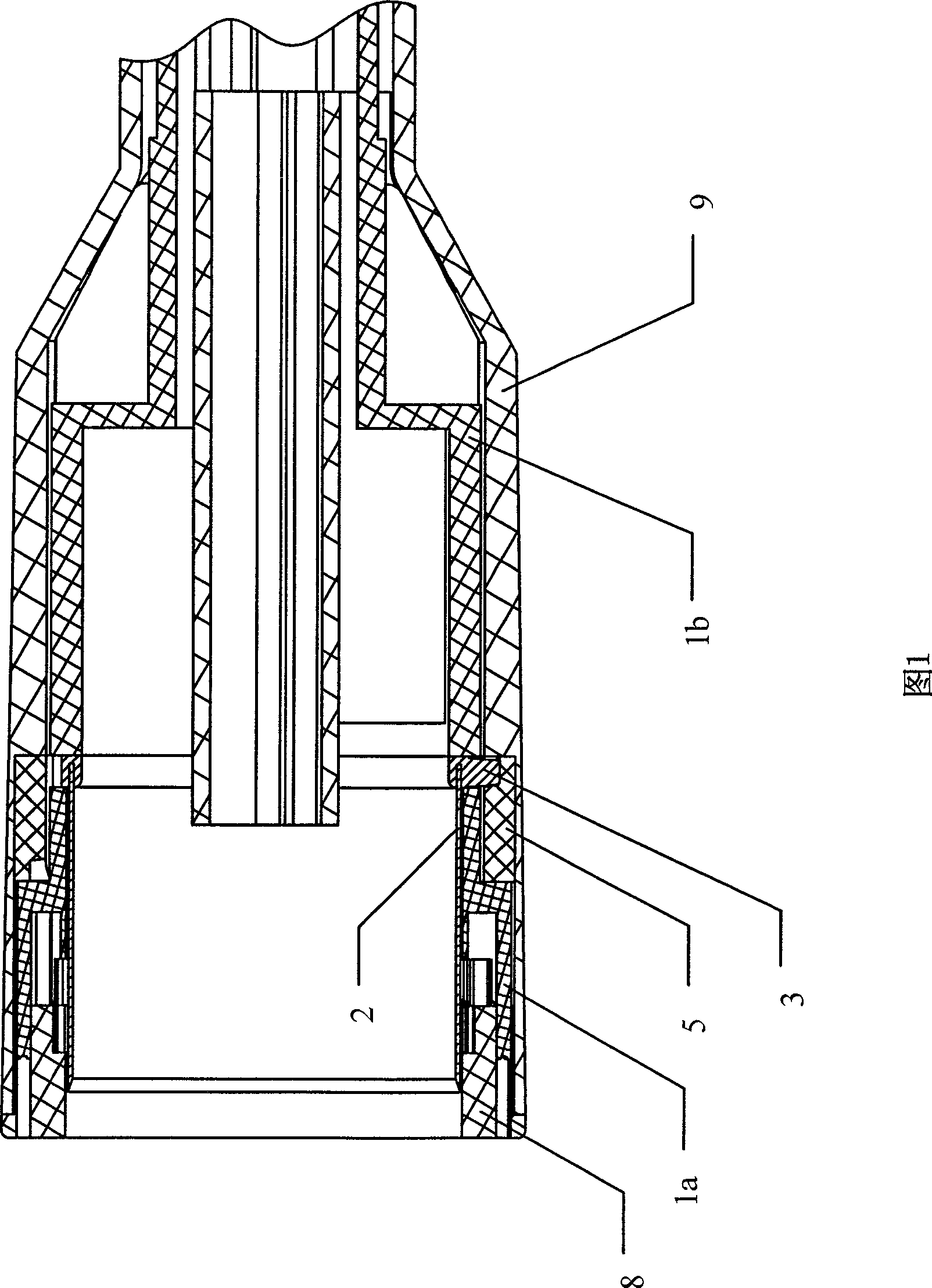
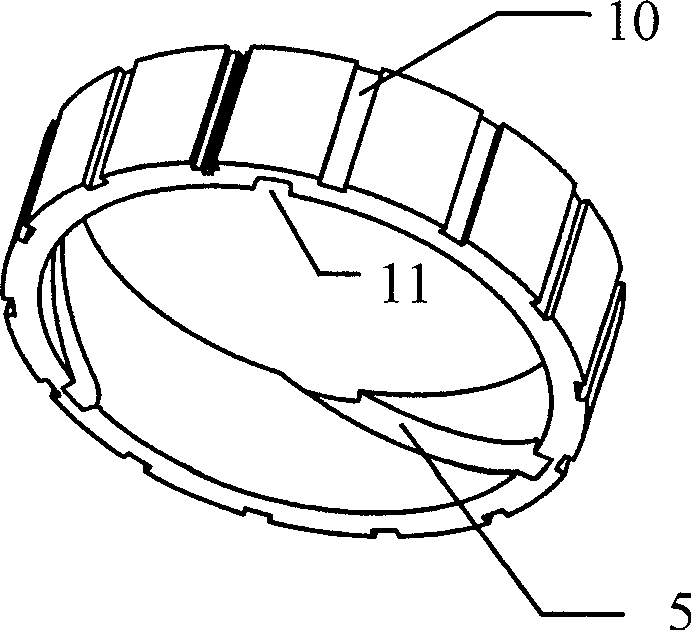
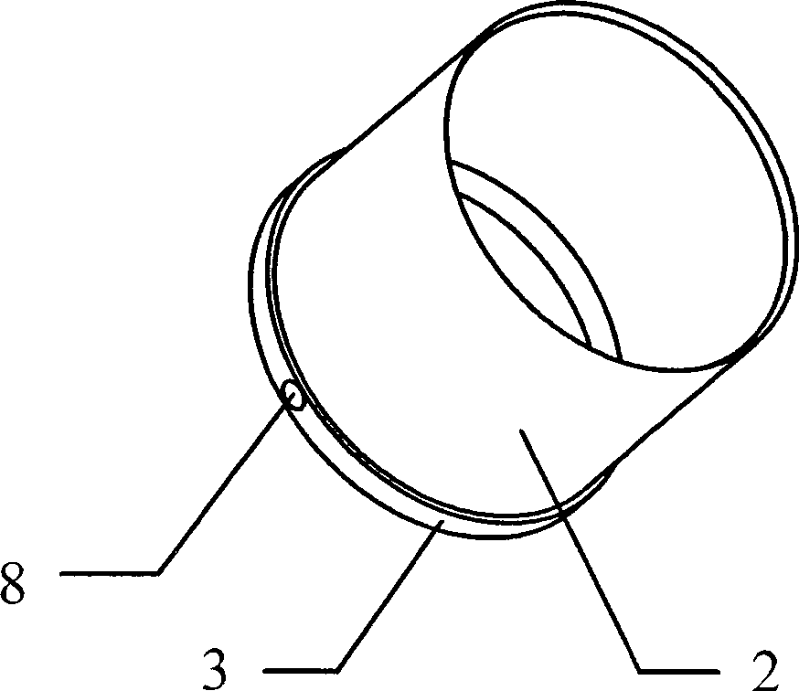
[0031] Figure 1~ Figure 4 , Image 6 , Figure 7The rotary cutter head shown includes a nail barrel 9, a knife seat 3, a nail pusher 1, and a nail bin 8, and the knife seat 3 is equipped with a ring knife 2, and the knife seat 3, the nail pusher 1 and the nail bin 8 are all set. Inside the nail cylinder 9, a complete stapler cutter head is formed. A split-type nail pusher is adopted, which is divided into an upper nail pusher 1a and a lower nail pusher 1b. First push down the nail piece 1b into the nail barrel 9, guide post 4 is provided on the outside of the knife seat 3, and place the track accessory block under the knife seat 3. Then, put the guide post 4 against the track accessory block and align it with the introduction port 11 provided at the front end of the threaded track 5, slowly rotate the tool holder 3 or the track accessory block, and store the tool holder 3 in the track accessory block. At the same time, insert the push-up nail piece 1a into the joint gap b...
Embodiment 2
[0033] Such as Figure 3 ~ Figure 5 As shown, the nail pusher 1 with an integrated structure has a relief groove 6 in the circumferential direction, and the number and position of the relief groove 6 are determined according to the number and position of the guide posts 4 on the tool holder. Since the nail pusher adopts an integrated structure, the knife seat 3 of the pluggable guide post 4 can be selected. First put the knife holder 3 into the front end of the nail pusher 1, let the guide post 4 pass through the relief groove 6 and insert it into the corresponding matching hole 7 on the knife holder, and then move the track accessory block upwardly from the tail end of the nail pusher 1 to the Align the guide post 4 with the lead-in port 11 at the front end of the threaded track 5 at the position of the step-off groove 6, and slowly rotate the pusher piece 1 or the track accessory block to realize the alignment of the track accessory block, the pusher piece 1, and the tool ho...
Embodiment 3
[0035] As shown in Figures 1 to 4, the rotary cutter head of the surgical stapler includes a nail barrel 9, a knife seat 3, a nail pusher 1, and a staple bin 8. The knife seat 3 is equipped with a ring-shaped knife 2, a knife seat 3, The nail pusher 1 and the staple magazine 8 are both placed in the nail barrel 9 to form a complete stapler cutter head. The threaded track 5 is directly provided on the inner wall of the nail barrel 9, and the guide post 4 is provided on the outside of the knife seat 3. , and the two are integrated, that is, they are cast into one. After assembling the knife holder 3 and the nail pushers 1a and 1b with the above method, align the guide post 4 with the inlet 11 of the threaded track, slowly rotate and move, and put the nail pusher and the knife holder 3 together into the nail cylinder 9 , because the guide post 4 cooperates with the threaded track 5 to make the knife seat 3 rotate along the threaded track 4, and the ring-shaped knife 2 is fixedly ...
PUM
 Abstract
Description
Claims
Application Information
 - R&D
- Intellectual Property
- Life Sciences
- Materials
- Tech Scout
- Unparalleled Data Quality
- Higher Quality Content
- 60% Fewer Hallucinations
Browse by: Latest US Patents, China's latest patents, Technical Efficacy Thesaurus, Application Domain, Technology Topic, Popular Technical Reports.
© 2025 PatSnap. All rights reserved.Legal|Privacy policy|Modern Slavery Act Transparency Statement|Sitemap|About US| Contact US: help@patsnap.com


