
A spraying device of mortar or concrete and a spraying method ofthe mortar or concrete using the device

A spraying device and concrete technology, which is applied to mixers with rotary stirring devices, clay preparation devices, cement mixing devices, etc., can solve the problems of impossibility, large pressure feeding resistance, and difficult spraying construction, so as to prevent clogging and improve Continuity of delivery, easily adjustable effect

Inactive Publication Date: 2009-03-04
NISSHOKU CORP TSUYAMA OKAYAMA JP
View PDF6 Cites 0 Cited by
  • Summary
  • Abstract
  • Description
  • Claims
  • Application Information

AI Technical Summary

Problems solved by technology

[0002] In the past, when spraying mortar or concrete on the pre-formed formwork on a high slope to form a grid-shaped slope protection, water, cement, and aggregates were mixed in advance to form the sprayed material, and the aforementioned sprayed material was sent by conveying pipes. In the mortar or concrete spraying device, the pressure feeding resistance of the above-mentioned spraying material passing through the conveying pipe is very large, and the spraying material cannot be discharged at the expected discharge volume (pressure). It is very difficult or even impossible to spray the material

Method used


Image

  • A spraying device of mortar or concrete and a spraying method ofthe mortar or concrete using the device
  • A spraying device of mortar or concrete and a spraying method ofthe mortar or concrete using the device
  • A spraying device of mortar or concrete and a spraying method ofthe mortar or concrete using the device

Examples


Embodiment Construction

[0060] Hereinafter, the implementation mode of the present invention will be described based on the drawings.

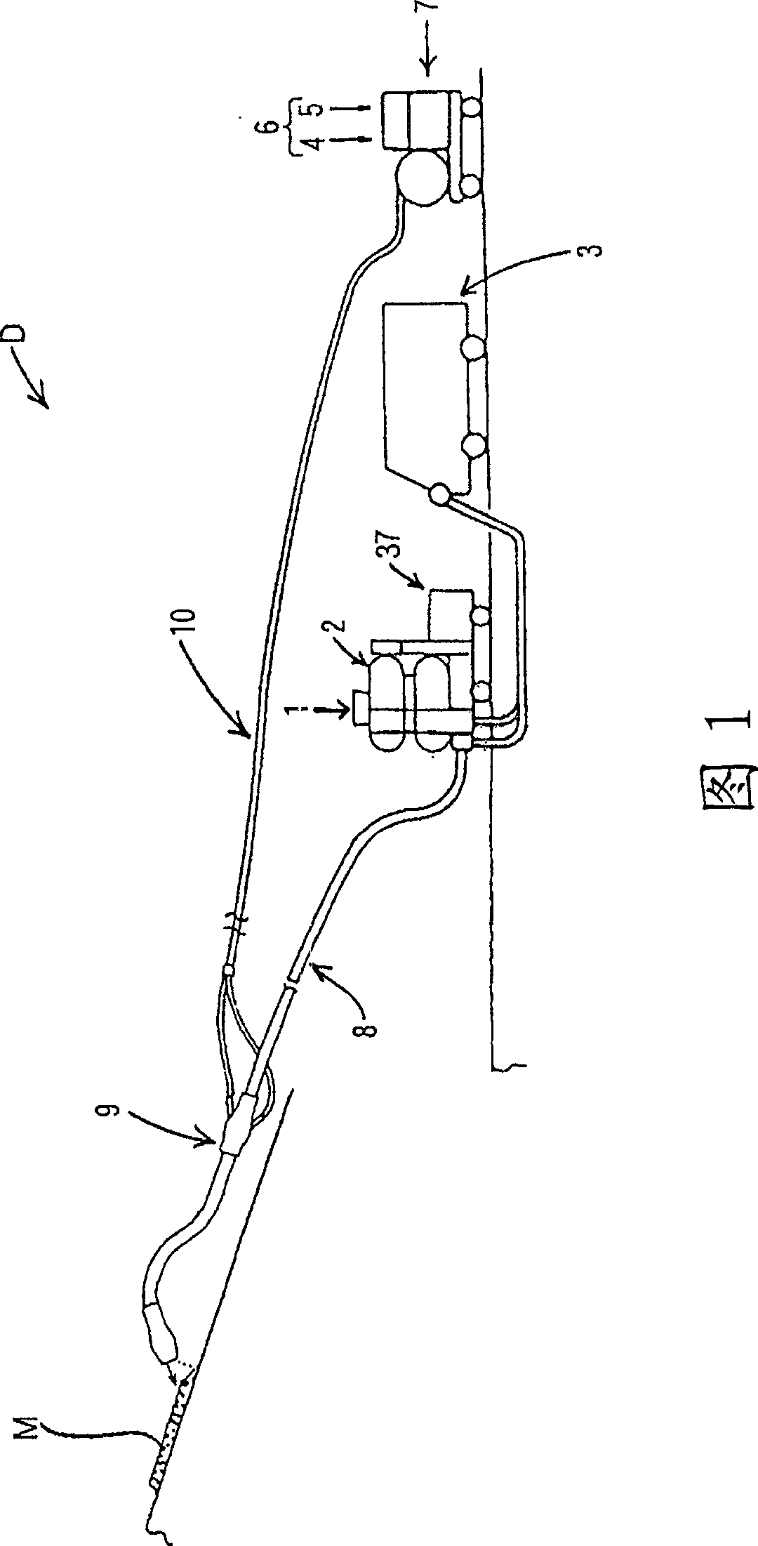
[0061] Figure 1 is an explanatory diagram schematically showing the construction of a mortar or concrete spraying device (hereinafter referred to as spraying device) D and method according to an embodiment of the present invention.

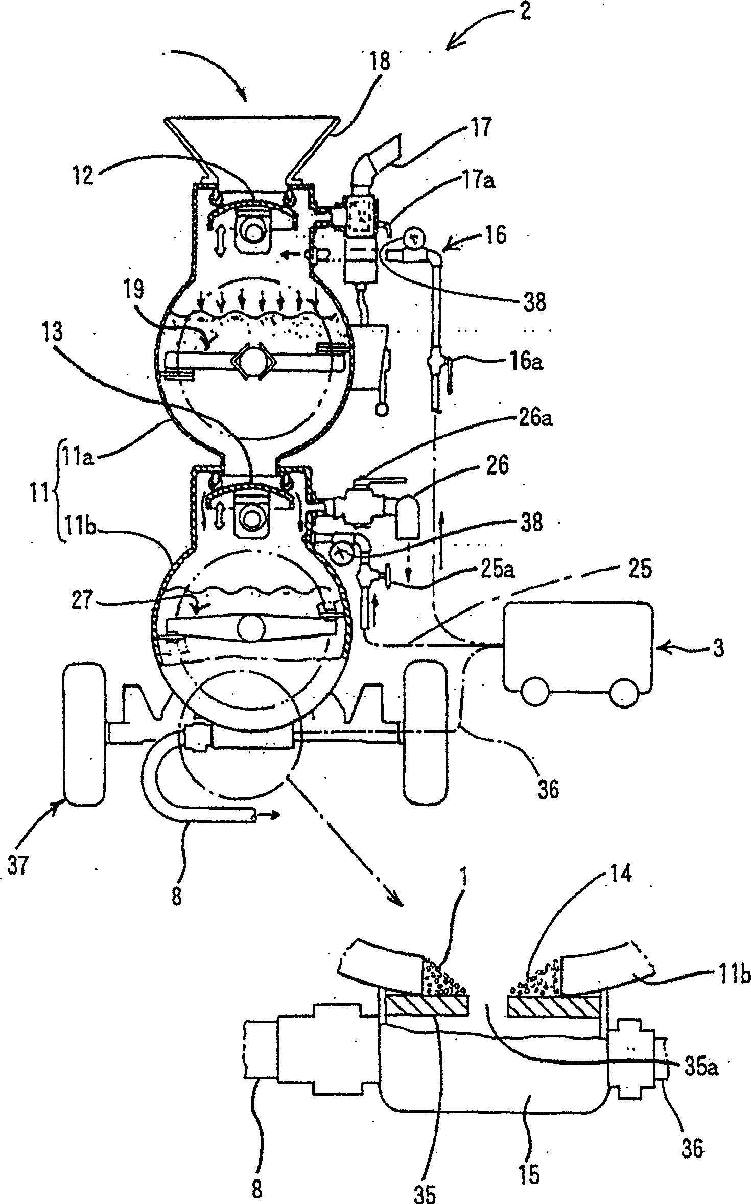
[0062] The spraying device D has: an aggregate pressing machine 2 for supplying aggregates (sand (fine aggregate) in the case of mortar M, and sand and gravel (thick aggregate) in the case of concrete) 1 Material supply mechanism; Air compressor 3, which is connected to the aggregate press 2 and used as a compressed air mechanism; Compression pump (such as piston pump, squeeze pump) 7, is used as a cement slurry delivery mechanism to deliver the mixed A cement slurry 6 made of cement 4 and water 5; a conveying pipe 8 is connected to the downstream side of the aforementioned aggregate press 2 and is provided with a cement slurry introduction ...


PUM


Abstract

A device for spraying mortar or concrete and a method of spraying mortar or concrete that enable smooth and reliable spray of mortar or concrete even if long distance transportation is involved. A device for spraying mortar or concrete, separately sending aggregate and cement milk forming mortar or concrete and then mixing them for spraying. The device has an aggregate pressure-sending machine for sending the aggregate by pressure and a transportation tube connected to the aggregate pressure-sending machine. The aggregate pressure-sending machine has a container for receiving the aggregate and a send-out section provided on the lower side of the container so as to communicate with the inside of the container through a communication opening. To the send-out section is connected the transportation tube. The aggregate dropped from the inside of the container to the send-out section through the communication hole provided in the bottom wall of the container is sent out into the transportation tube. The opening area of the communication hole is not more than the area of a flow path in the transportation tube.

Description

Technical field [0001] The invention relates to a mortar or concrete spraying device and a mortar or concrete spraying method using the device. Background technique [0002] In the past, when mortar or concrete was sprayed on a preformed formwork at a high place to form a grid-like slope protection, water, cement, and aggregates were mixed in advance to form the spraying material, and the aforementioned spraying material was sent by pressure through a conveying pipe. In the mortar or concrete spraying device, the pressure resistance of the aforementioned spraying material in the conveying pipe is very large, and the spraying material cannot be discharged at the expected discharge volume (pressure). Therefore, spraying at high places or using large-size bone The spraying of materials is very difficult or even impossible. [0003] Therefore, the applicant of this application is developing a cement that can be used to form mortar or concrete as shown in Patent Document 1 below in or...

Claims


Application Information

Patent Timeline
Patent Type & Authority Patents(China)
IPC IPC(8): E02D17/20B01F7/00B01F7/04B01F13/10B01F15/00B01F15/02B28C5/12
CPCB01F7/00275B28C5/1276B01F13/1016B01F7/00175B01F15/0288B28C5/1261B01F13/1013B01F7/04B01F7/00025A61P31/04B01F27/052B01F27/0727B01F27/1123B01F27/70B01F33/811B01F33/81B01F35/75455E02D17/202E02D17/205E02D17/207E02D2300/0018
Inventor 大仓卓雄杉本胜弘藤岛泰良坂本悟
Owner NISSHOKU CORP TSUYAMA OKAYAMA JP
Learn More