Waste-water return-flow system flow compensation method and flow compensation valve
A technology of flow compensation and system flow, applied in the field of flow compensation valve, which can solve the problems of increasing water resistance, decreasing water resistance, unable to maintain a constant waste water ratio, etc.
- Summary
- Abstract
- Description
- Claims
- Application Information
AI Technical Summary
Problems solved by technology
Method used
Image

Examples
Embodiment 1
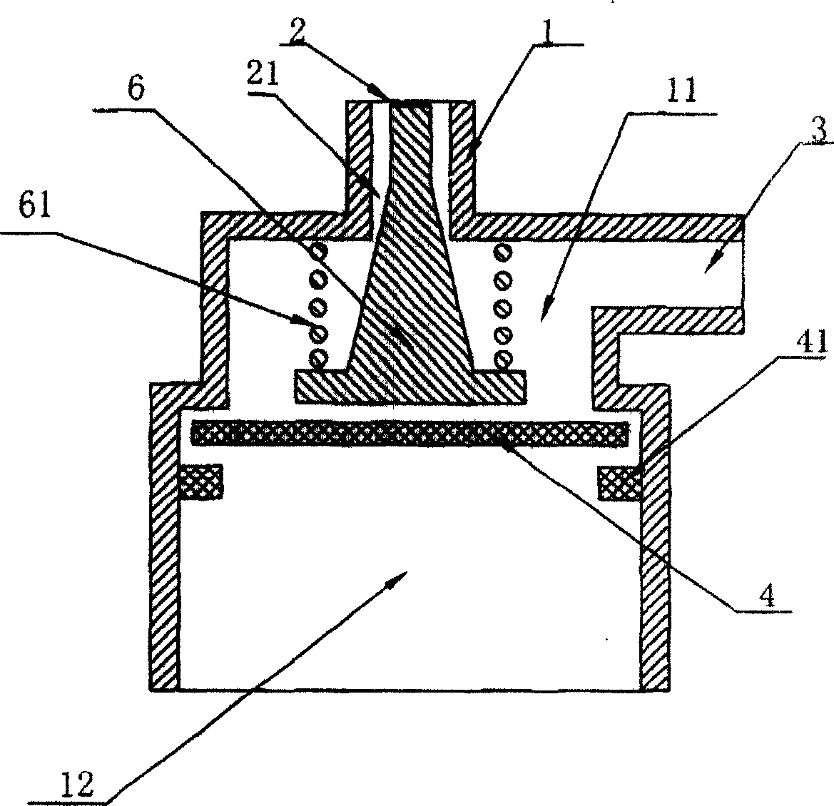
[0031] Such as figure 1 As shown, the first embodiment includes a valve body 1, the valve body 1 is provided with an inner cavity, and the valve body 1 is provided with a water inlet 2 and a water outlet 3 that can communicate with the inner cavity. , a water inlet channel 21 connected to the water inlet 2 is provided, an elastic diaphragm 4 is arranged in the inner cavity, and its periphery is fixed on the upper diaphragm pressure ring 41 provided in the inner cavity of the valve body 1, and the inner cavity is isolated as The upper chamber 11 and the lower chamber 12, the water inlet channel 21 is a long and thin through hole, the water inlet 2, the water inlet channel 21, and the water outlet 3 are all placed in the upper chamber of the valve body 1. In the upper chamber 11, there is a tapered control rod 6, the upper end of which is placed in the water inlet channel 21. The gap in the gap forms a waste water channel, and the lower end is located above the elastic diaphrag...
Embodiment 2
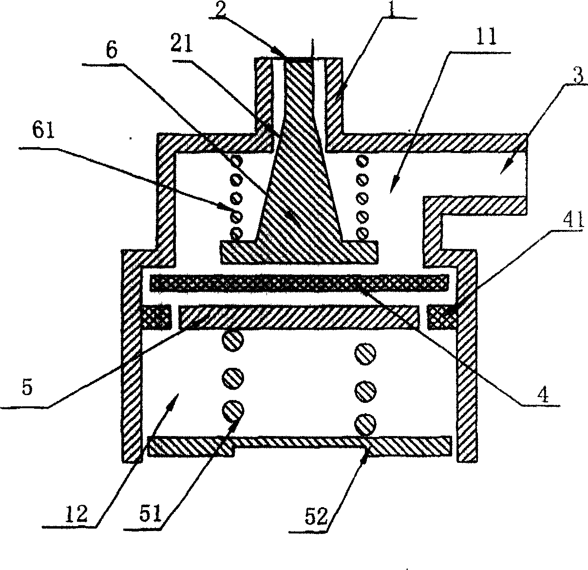
[0037] Such as figure 2 As shown, the structure of the valve body 1 and the control rod 6 of the second embodiment are the same as those of the first embodiment, the difference is that the lower chamber 12 of the present embodiment is provided with a supporting plate 5 that can touch the top of the elastic diaphragm 4, and place Below the elastic diaphragm 4 , the supporting plate 5 is fixed on the valve body 1 through the supporting plate spring 51 .
[0038] In the normal state, the pretension force of the supporting plate spring 51 gives the elastic diaphragm 4 an upward supporting force through the supporting plate 5. This supporting force can be in a balanced state with the hydraulic pressure that the elastic diaphragm 4 bears. The elastic force of the spring 61 and the control The water pressure that rod 6 bears keeps balance, and elastic diaphragm 4 and control rod 6 have no displacement.
[0039] When the water pressure fluctuates, the working principle of this embod...
Embodiment 3
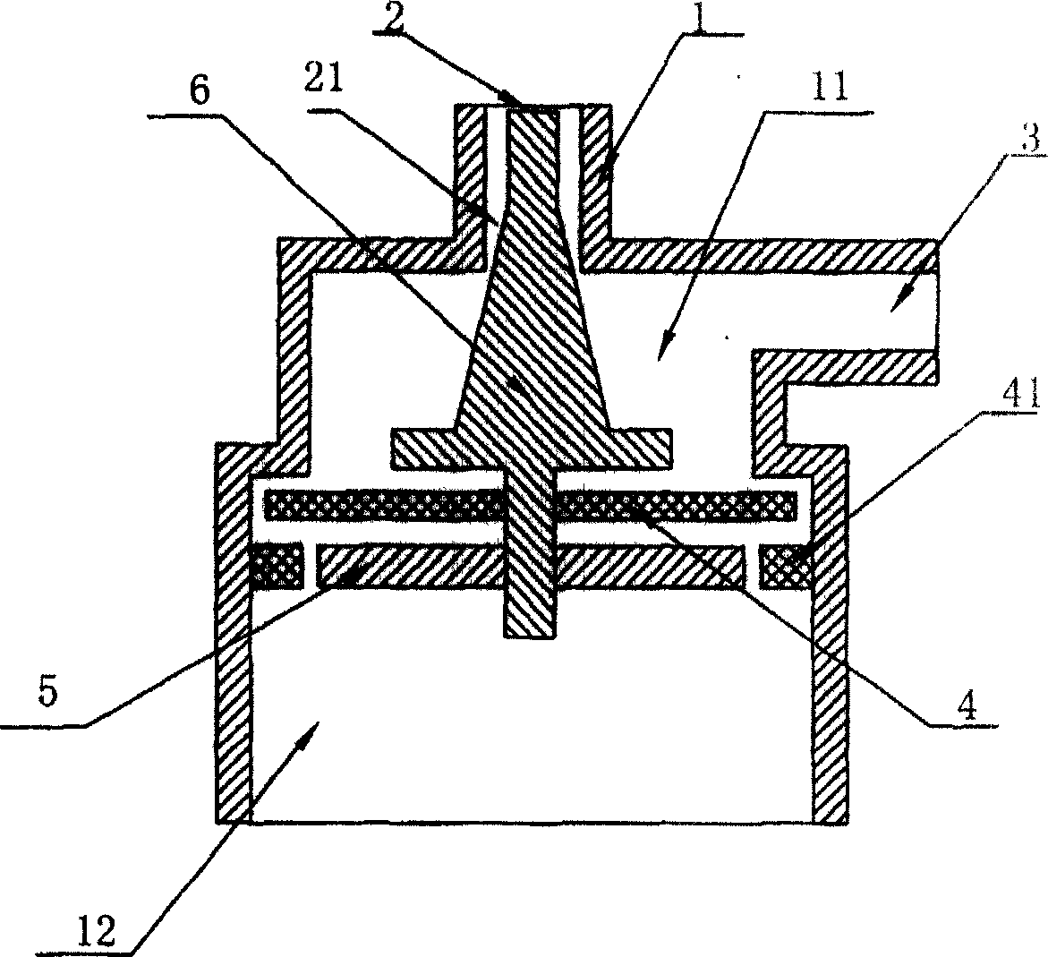
[0042] Such as image 3 As shown, the valve body 1 of the third embodiment of the present embodiment is the same as that of the first and second embodiments, and the control rod 6 is also a tapered rod. Placed in the water inlet channel 21 , the gap between it and the water inlet channel 21 is tapered, and the lower end passes through the elastic diaphragm 4 and is fixedly connected to the supporting plate 5 . As the control rod 6 moves up and down in the water inlet channel 21, the gap between it and the water inlet channel 21 also changes accordingly, thereby adjusting the water resistance and flow.
[0043] The working principle of this embodiment is as follows:
[0044] When the pressure of the water outlet 3 is equal to the set value, the elastic force of the elastic diaphragm 4 is balanced with the water pressure of the upper chamber 11, and the elastic diaphragm 4 and the control rod 6 have no displacement.
[0045] When the pressure of the water outlet 3 increases an...
PUM
 Abstract
Description
Claims
Application Information