Lifting mechanism of physical gas-phase deposition

A technology of physical vapor deposition and lifting mechanism, which is applied in the field of lifting mechanism, can solve the problem that the electric charge cannot be released, and achieve the effect of reducing wear and tear

Inactive Publication Date: 2009-04-08
CHUNGHWA PICTURE TUBES LTD
View PDF4 Cites 0 Cited by
  • Summary
  • Abstract
  • Description
  • Claims
  • Application Information

AI Technical Summary

Problems solved by technology

[0007] Therefore, the main purpose of the present invention is to provide a claw applied to a physical vapor deposition device to improve the problem that the traditional ceramic claw cannot be released due to long-term friction

Method used


Image

  • Lifting mechanism of physical gas-phase deposition
  • Lifting mechanism of physical gas-phase deposition
  • Lifting mechanism of physical gas-phase deposition

Examples


Embodiment Construction

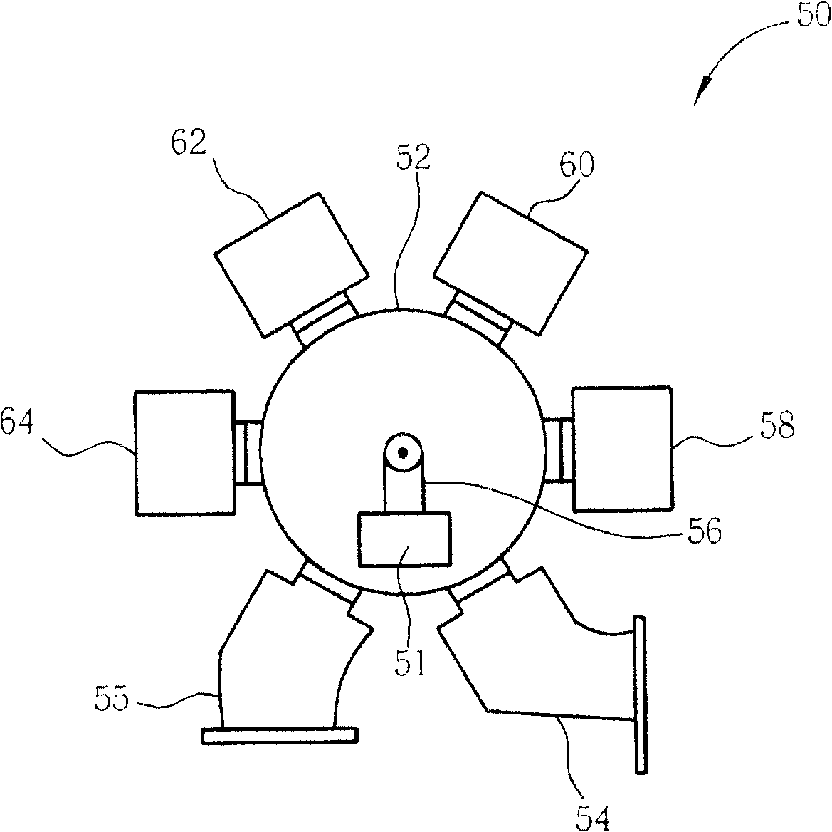
[0026] As mentioned above, before performing the physical vapor deposition process, all the glass substrates need to be loaded into the heating chamber for a preheating action. After the glass substrates are heated, the glass substrates are sent to the sputtering chambers respectively. Substrate film formation works, and these actions use ceramic claws to lift the glass substrate and place it on the glass substrate carrier.

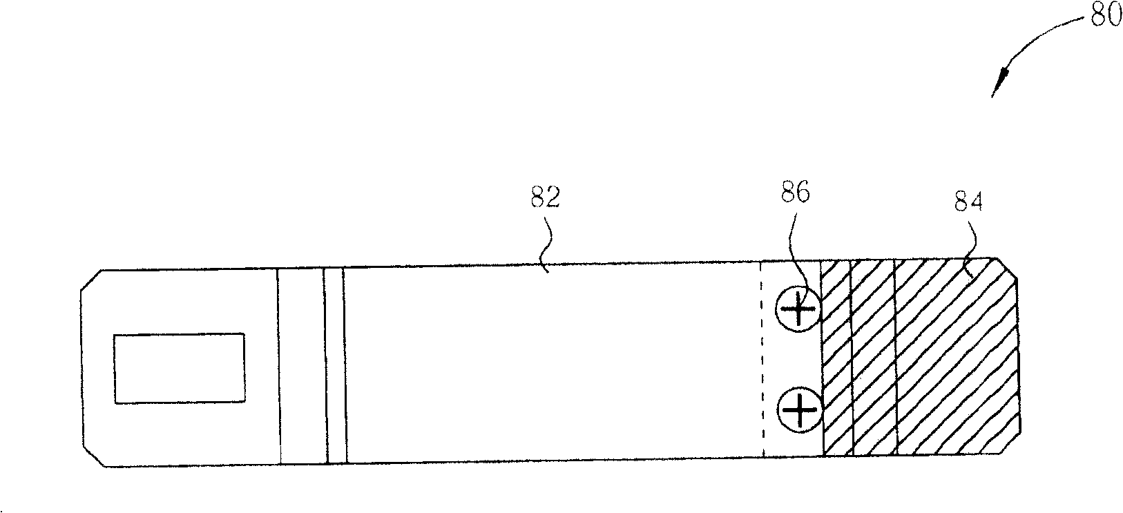
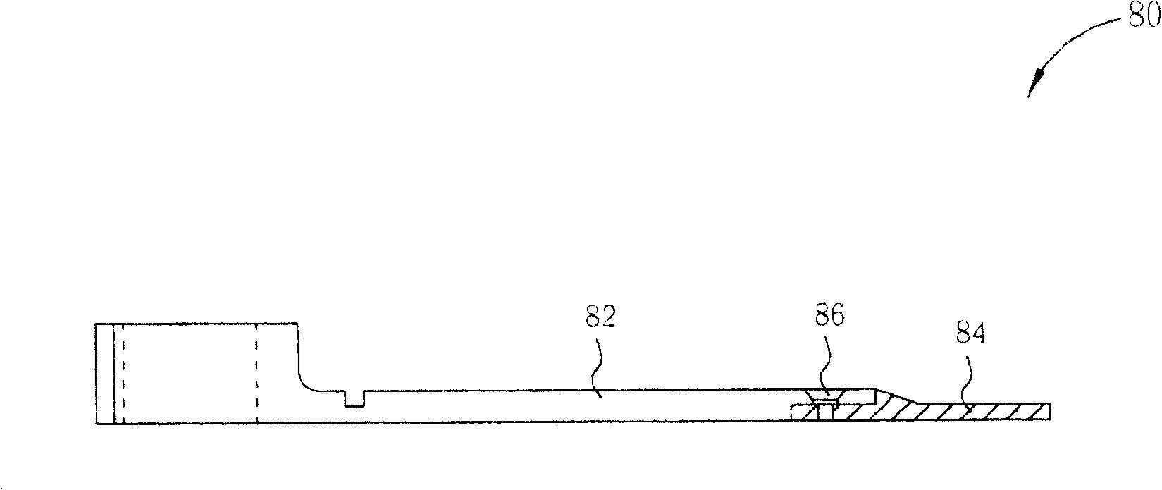
[0027] Please refer to figure 2 and image 3 , figure 2 It is the upper view of the ceramic claw 80 of the present invention, and image 3 It is a side view of the ceramic claw 80 of the present invention. Such as figure 2 and image 3 As shown, the ceramic hook 80 of the present invention includes a ceramic body 82 and a metal plate 84 . Wherein, the ceramic main body 82 includes a front end and a rear end, and the metal plate 84 is detachably connected to the front end of the ceramic main body 82 by at least one Phillips flat head screw 86 . I...


PUM


Abstract

A kind of physics gas phase aggradation promotion and demotion organization, it includes a glass board load base, a promotion and demotion device which is fixed in both ends of the glass board load base, and a falcula which is linked in the promotion and demotion device. The falcula includes a ceramic main body, the ceramic main body includes one fore-end and one trailing end, an electric conduction film covers in the surface of the ceramic main body, and a metal plate links in the fore-end of the ceramic main body.

Description

technical field [0001] The present invention relates to a physical vapor deposition device, in particular to a lifting mechanism applied to a physical vapor deposition device. Background technique [0002] Physical vapor deposition (PVD) technology is a thin film deposition technology carried out by physical deposition procedures, which is widely used in the production processes of thin film transistor liquid crystal display (TFT LCD), plasma display panel (PDP) and semiconductor, and such as As known to those in the industry, physical vapor deposition can be roughly divided into two forms: evaporation and sputtering. Among them, evaporation uses resistance or electron beams to heat an evaporation source, and then uses the saturated vapor pressure of the evaporation source at high temperature to deposit a thin film. The sputtering uses a potential gradient to accelerate heavier inert elements, such as argon (Ar+) ions, to hit the metal target, so that the metal atoms of the...

Claims


Application Information

Patent Timeline
Patent Type & Authority Patents(China)
IPC IPC(8): C23C14/56
Inventor 徐文懋欧政霖林信宏
Owner CHUNGHWA PICTURE TUBES LTD
Why Eureka
Try Eureka