Method and device for controlling ATM network flow based on FPGA

A network flow and flow control technology, applied in data exchange networks, digital transmission systems, electrical components, etc., can solve problems such as high costs and complex systems, save system costs, accurately control ATM cell rates, and improve system reliability. Sexuality and Market Competitiveness

Inactive Publication Date: 2009-05-06
ZTE CORP
View PDF5 Cites 1 Cited by
  • Summary
  • Abstract
  • Description
  • Claims
  • Application Information

AI Technical Summary

Problems solved by technology

[0004] The technical problem to be solved by the present invention is to provide a device and method for realizing ATM network flow control based on FPGA, which is used to overcome the fact that the ATM network flow control in the router existing in the prior art is realized by a dedicated SAR chip, causing system complexity, Cost-prohibitive problems and flaws

Method used


Image

  • Method and device for controlling ATM network flow based on FPGA
  • Method and device for controlling ATM network flow based on FPGA
  • Method and device for controlling ATM network flow based on FPGA

Examples


Embodiment Construction

[0042] The implementation of the technical solution for implementing ATM network flow control based on FPGA will be further described in detail below with reference to the accompanying drawings.

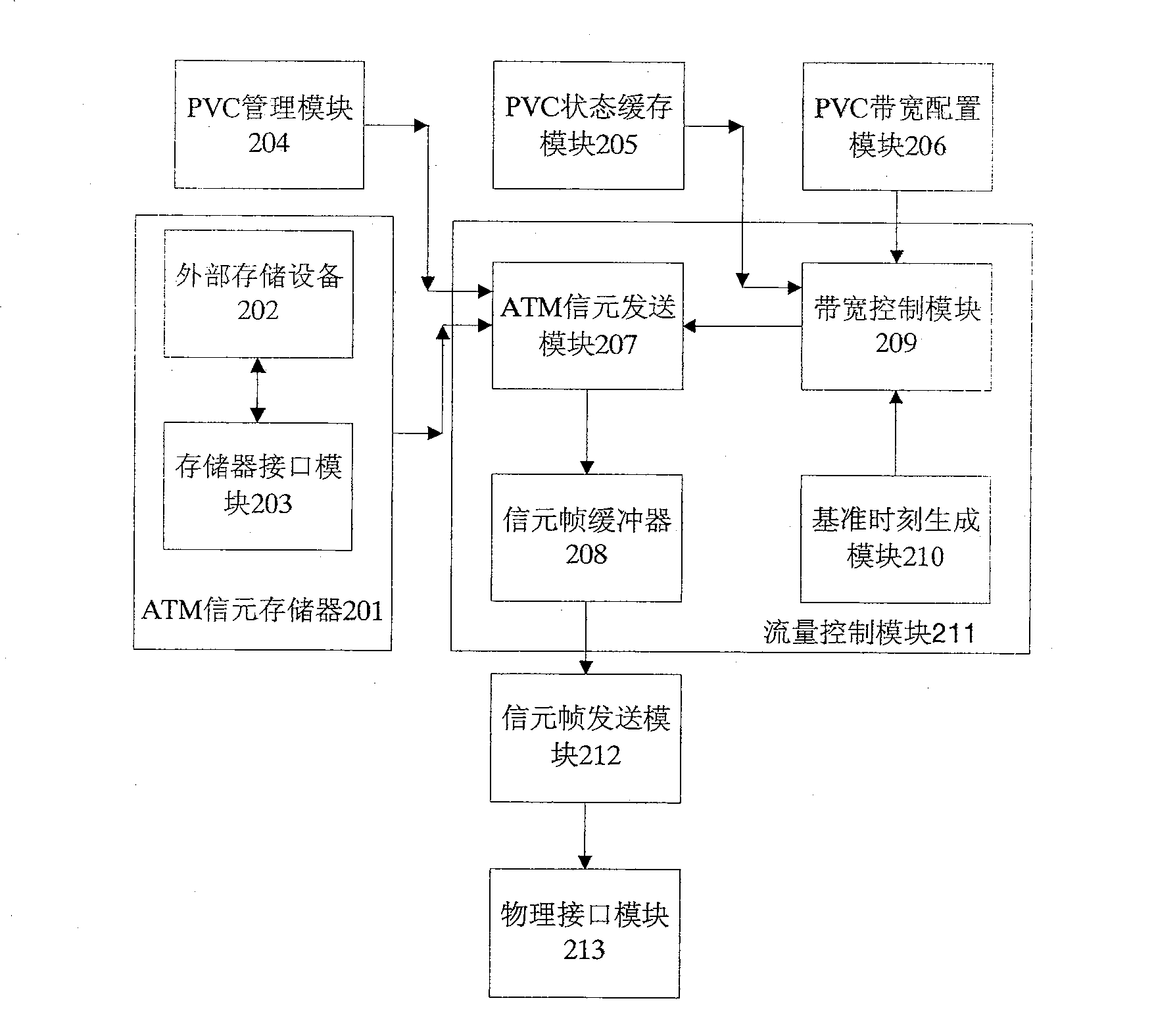
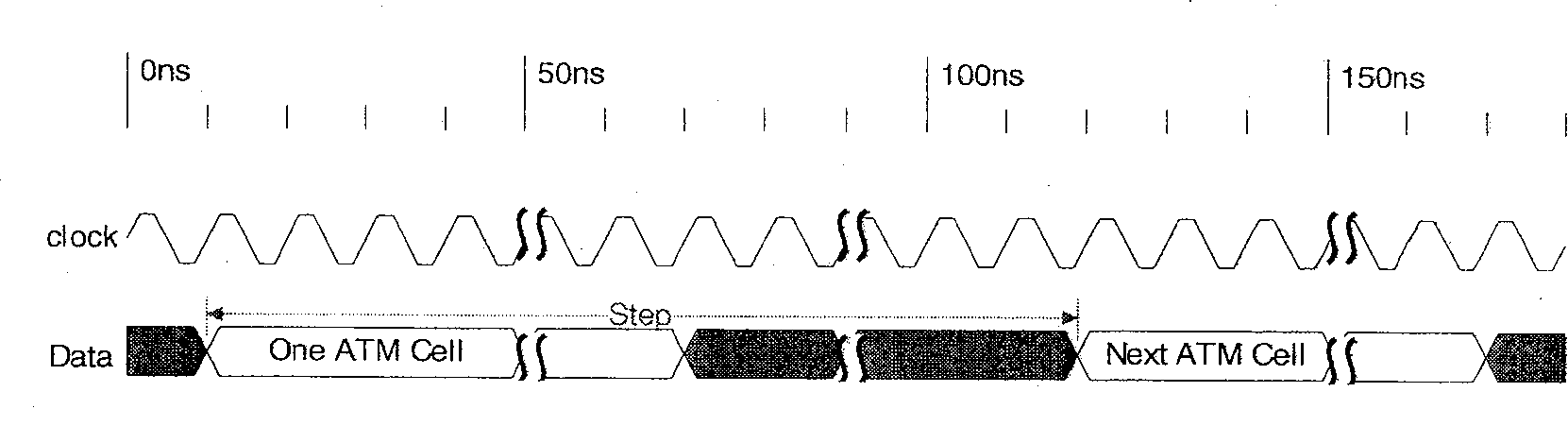
[0043] see figure 2 Shown is the ATM network flow control module diagram of the present invention; image 3 It is a schematic diagram of the PVC bandwidth configuration parameters used in the present invention; Figure 4 It is a schematic diagram of cell frame encapsulation used in the present invention. The device for realizing ATM network flow control based on the FPGA of the present invention includes: a hardware module part and a software module part.

[0044] The hardware module part includes: ATM cell memory 201 , including an external storage device 202 and a memory interface module 203 . The external storage device 202 is a large-capacity RAM (Random Access Memory, random access memory), used to store ATM cells; the memory interface module 203 is an interface module for d...


PUM


Abstract

This invention discloses the realizing ATM network flow control device and method based on FPGA.

Description

technical field [0001] The invention relates to the technical field of realizing flow control in routers, in particular to a device and method for realizing flow control of ATM networks based on FPGA on routers. Background technique [0002] With the development of computing technology, various data transmission networks have emerged. At present, there are mainly two types of networks, one is a packet-based IP (Internet Protocol, Internet Protocol) packet network, and the other is a cell-based transmission ATM (Asynchronous Transfer Mode, Asynchronous Transfer Mode) network. As a router based on IP packet switching, when connecting to an ATM network, a line interface card for processing IP packet to ATM cell conversion is required. [0003] The current ATM line interface card is mainly composed of (such as figure 1 shown) optical module 101, physical layer chip 102, SAR (Segment And Reassemble, segmentation / reassembly or disassembly) chip 103, FPGA (Field Programmable Gate...

Claims


Application Information

Patent Timeline
Patent Type & Authority Patents(China)
IPC IPC(8): H04L12/56H04L12/801
Inventor 郑斌儒周广水李祥
Owner ZTE CORP
Why Eureka
Try Eureka