

Internal cavity pressure limiting valve
A technology of pressure limiting valve and inner cavity, which is applied in the structural field of inner cavity pressure limiting valve, can solve problems such as little effect, damage to pressure limiting valve, and reduced service life
- Summary
- Abstract
- Description
- Claims
- Application Information
AI Technical Summary
Problems solved by technology
Method used
Image

Examples
Embodiment 1
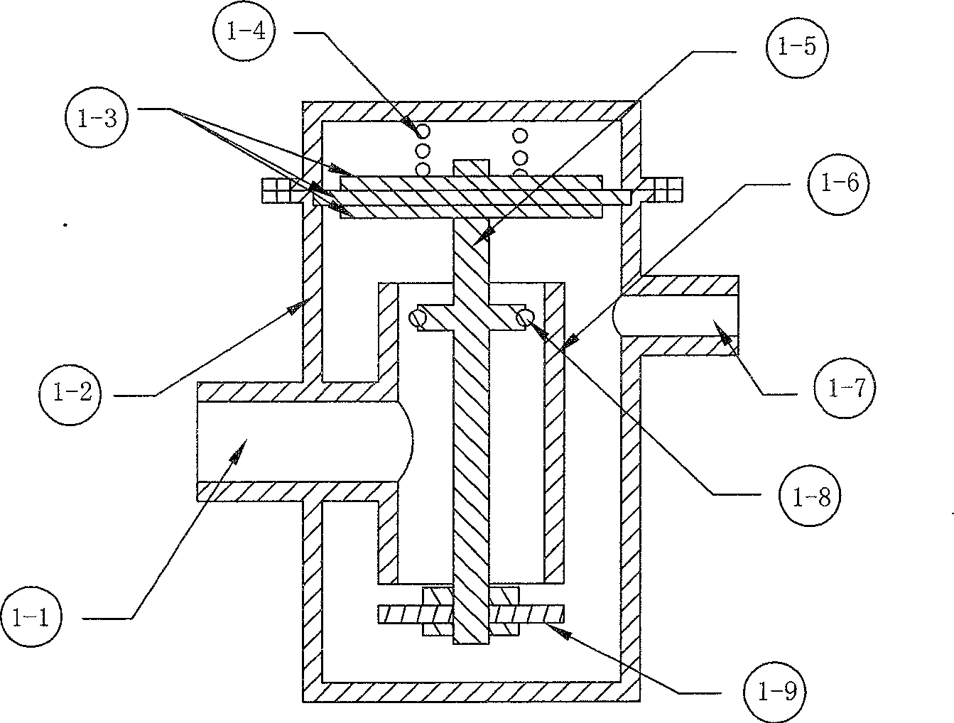
[0023] In the first embodiment, the inner cavity is a straight-through structure with a single valve port and a single blocking member. Such as figure 1 As shown, there is a water inlet 1-1 and a water outlet 1-7 on the valve body 1-2, the water inlet 1-1 communicates with the inner cavity 1-6, and the inner cavity 1-6 is a straight-through structure, with an upper , the lower two straight openings, the control rod assembly 1-5 is a through rod in this embodiment, passing through the cavity of the inner cavity 1-6, the lower end is connected with the blocking member 1-9, and the middle position is fixedly connected with a belt The upper end of the piston 1-8 of the sealing ring is fixedly connected with the pressure limiting assembly 1-3, the pressure limiting assembly 1-3 is fixedly connected with the valve body 1-2, and the top of the pressure limiting assembly 1-3 supports the spring 1-4 (of course, Also can be provided with spring on the control lever assembly, or both ar...
Embodiment 2
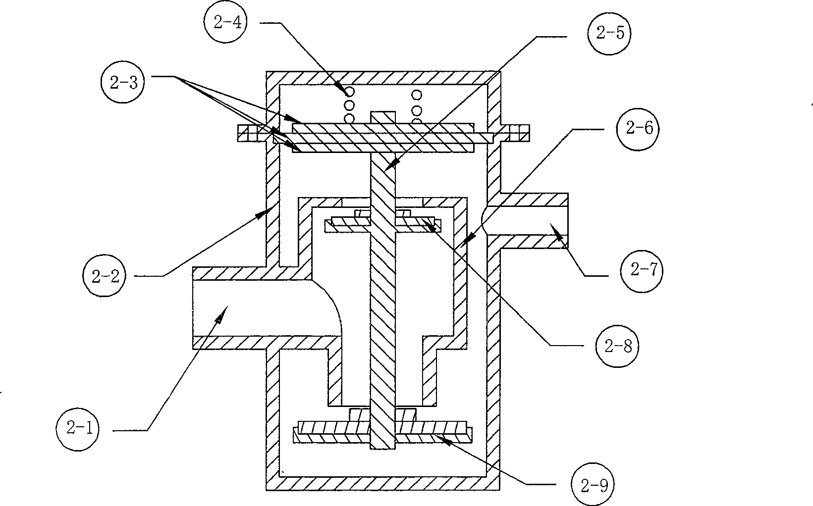
[0025] In the second embodiment, the inner cavity is a straight-through structure with double valve ports and double blocking parts. Such as figure 2As shown, there is a water inlet 2-1 and a water outlet 2-7 on the valve body 2-2, the water inlet 2-1 communicates with the inner cavity body 2-6, and the inner cavity body 2-6 has two straight openings up and down, The control rod assembly 2-5 is also a through rod, passing through the cavity of the inner cavity 2-6, the lower end is connected with the blocking piece 2-9, and the middle position is also fixedly connected with a blocking piece 2-8, and the upper end is connected with the pressure limiting assembly 2-3 is fixedly connected, the pressure limiting component 2-3 is fixedly connected with the valve body 2-2, and the pressure limiting component 2-3 supports the spring 2-4 above. Among them, the blocking part 2-8 is located inside the upper opening of the inner cavity 1-6, and the upper opening of the inner cavity 2-6...
Embodiment 3
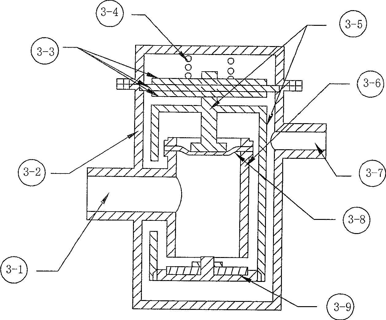
[0028] The inner cavity of the third embodiment of the present invention is another straight-through structure with a single valve port and a single blocking member. Such as image 3 As shown, there is a water inlet 3-1 and a water outlet 3-7 on the valve body 3-2, the water inlet 3-1 communicates with the inner cavity body 3-6, and the inner cavity body 3-6 has two straight openings up and down, The control rod assembly 3-5 is arranged on the outside of the inner cavity 3-6, and its bottom end is provided with a blocking member 3-9, and the blocking member 3-9 is located outside the lower opening of the inner cavity 3-6. The upper end of -5 is provided with a protruding rod, which supports or is fixedly connected with a pressure-sensitive component 3-8. —6 The upper opening is fixedly connected; the upper end of the control rod assembly 3-5 is also provided with an upper extension rod, which is supported or fixedly connected with the pressure limiting assembly 3-3 to form a ...
PUM
 Abstract
Description
Claims
Application Information