

Series resonant high-frequency chain sinusoidal wave inverse power supply circuit
A technology of series resonance and inverter power supply, which is applied in the direction of high-efficiency power electronic conversion, irreversible DC power input conversion to AC power output, electrical components, etc., which can solve the problem of increasing the difficulty of transformer design, the complexity of circuit work, and inverters. Problems such as low transmission efficiency and complex circuit structure achieve the effect of reducing the number of winding turns, simple control logic, and simplified circuit structure
- Summary
- Abstract
- Description
- Claims
- Application Information
AI Technical Summary
Problems solved by technology
Method used
Image

Examples
Embodiment 1
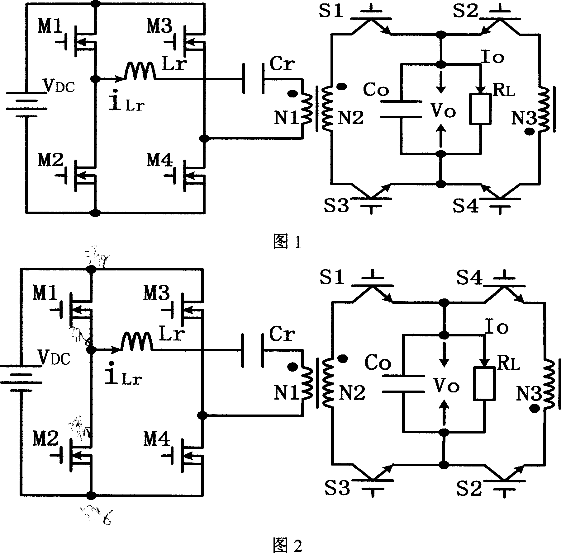
[0020] In Fig. 1, the front-end full-bridge inverter circuit adopts a full-bridge structure composed of the first to fourth front-stage power tubes, and the DC input power V DC The anode of the positive pole is connected to the drains of the first pre-stage power tube M1 and the third pre-stage power tube M3, and the negative pole is connected to the source of the second pre-stage power tube M2 and the fourth pre-stage power tube M4; the series resonant inductance L r One end is connected to the source of the first pre-stage power tube M1 and the drain of the second pre-stage power tube M2, and the other end is connected to the series resonant capacitor C r One end of the high frequency transformer is connected; the same name end of the primary winding N1 of the high frequency transformer is connected with the series resonant capacitor C r The other end is connected, and the opposite end is connected to the source of the third pre-stage power tube M3 and the drain of the fourt...
Embodiment 2
[0025] In Fig. 2, the front full bridge inverter circuit adopts a full bridge structure composed of the first to fourth front power tubes, and the DC input power V DC The anode of the positive pole is connected to the drains of the first pre-stage power tube M1 and the third pre-stage power tube M3, and the negative pole is connected to the source of the second pre-stage power tube M2 and the fourth pre-stage power tube M4; the series resonant inductance L r One end is connected to the source of the first pre-stage power tube M1 and the drain of the second pre-stage power tube M2, and the other end is connected to the series resonant capacitor C r One end of the high frequency transformer is connected; the same name end of the primary winding N1 of the high frequency transformer is connected with the series resonant capacitor C r The other end is connected, and the opposite end is connected to the source of the third pre-stage power tube M3 and the drain of the fourth pre-stag...
Embodiment 3
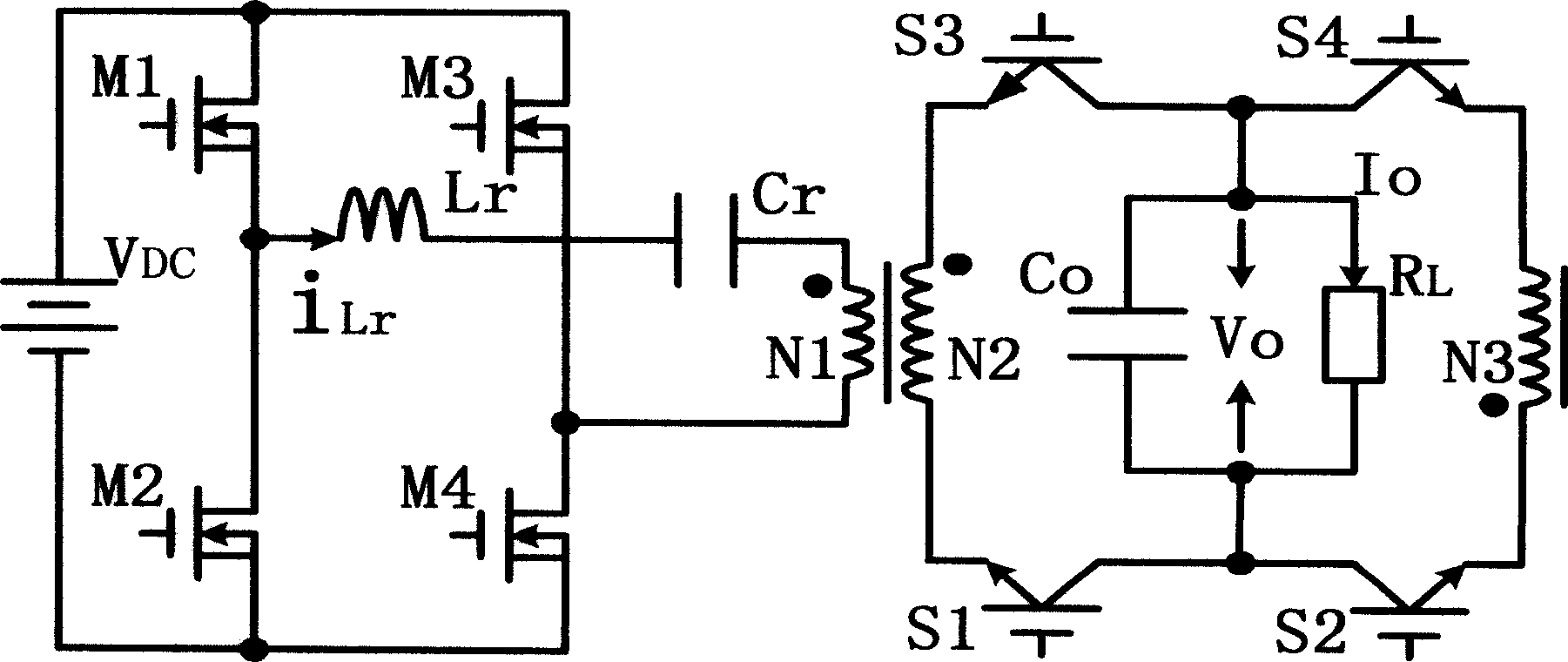
[0030] exist image 3 Among them, the front-stage full-bridge inverter circuit adopts a full-bridge structure composed of the first to fourth front-stage power tubes, and the DC input power V DC The anode of the positive pole is connected to the drains of the first pre-stage power tube M1 and the third pre-stage power tube M3, and the negative pole is connected to the source of the second pre-stage power tube M2 and the fourth pre-stage power tube M4; the series resonant inductance L r One end is connected to the source of the first pre-stage power tube M1 and the drain of the second pre-stage power tube M2, and the other end is connected to the series resonant capacitor C r One end of the high frequency transformer is connected; the same name end of the primary winding N1 of the high frequency transformer is connected with the series resonant capacitor C r The other end is connected, and the opposite end is connected to the source of the third pre-stage power tube M3 and the ...
PUM
 Abstract
Description
Claims
Application Information