
Technique for assembling subassembly of bottom valve of condensation damper valve in hydraulic damper

A technology of hydraulic shock absorber and assembly process, which is applied in the direction of assembly machines, manufacturing tools, metal processing equipment, etc. It can solve the problems of reducing compression damping force, reducing the consistency of damping force, damping force value attenuation, etc., and achieving improved compression The effect of damping force value, increasing compression damping force, and small attenuation of damping force value

Inactive Publication Date: 2009-06-03
隆昌山川减振器工业有限公司
View PDF4 Cites 0 Cited by
  • Summary
  • Abstract
  • Description
  • Claims
  • Application Information

AI Technical Summary

Problems solved by technology

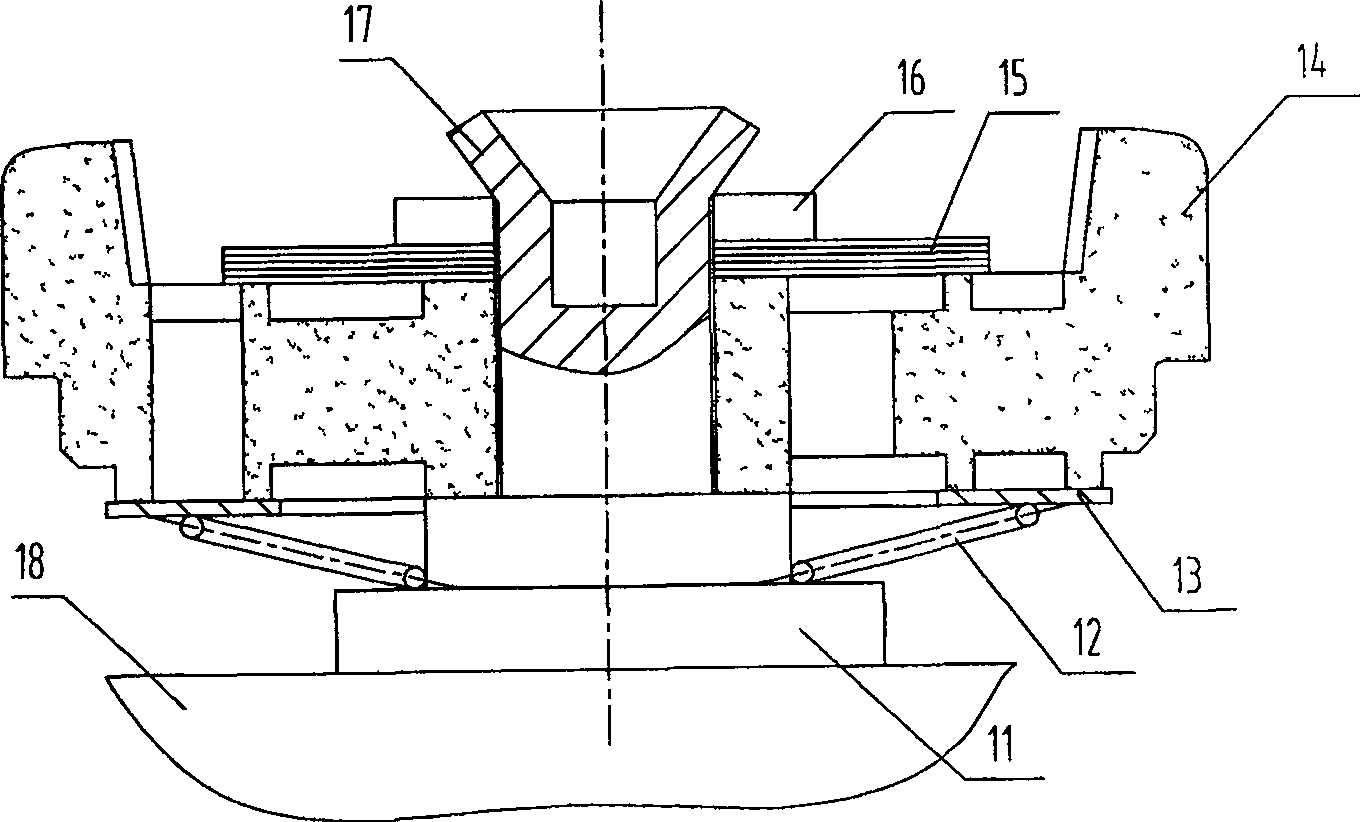
[0005] The disadvantages of this assembly process are: 1. Since the bottom valve seat 14 and the bottom valve stem 11 adopt clearance fit, after punching and riveting, there is a gap between the bottom valve seat 14 and the bottom valve stem 11 adjacent circumferential surfaces, causing oil leakage during use , the compression damping force is reduced, and due to the individual differences in the gap value, the consistency of the damping force is reduced, and the consistency of the product's vibration damping performance cannot be guaranteed;
[0006] 2. Due to the unstable deformation of the bottom valve stem 11 during punching and riveting, it is easy to cause instability of the compression damping force value, which affects the consistency of the product's damping performance; and because only the cone 17 is used to fix the baffle 16 and The damping valve plate 15, the cone 17 and the baffle plate 16 are in line contact, the contact area is small, and it is easy to deform after long-term use. The damping valve plate 15 and the baffle plate 16 are easy to loosen. The damping valve plate 15 and the bottom valve seat 14 fit together The tightness will be reduced, causing the damping force value to attenuate and the durability performance to decrease;
[0007] 3. Since there is no tooling for positioning each part, the bottom valve stem and the bottom valve seat are in a gap fit, and the parts are loose. In addition to the elastic force of the spring, it is easy to cause some parts to be misplaced during riveting. Scrap, low pass rate

Method used


Image

  • Technique for assembling subassembly of bottom valve of condensation damper valve in hydraulic damper
  • Technique for assembling subassembly of bottom valve of condensation damper valve in hydraulic damper
  • Technique for assembling subassembly of bottom valve of condensation damper valve in hydraulic damper

Examples


Embodiment Construction

[0019] The present invention will be further described below in conjunction with accompanying drawing.

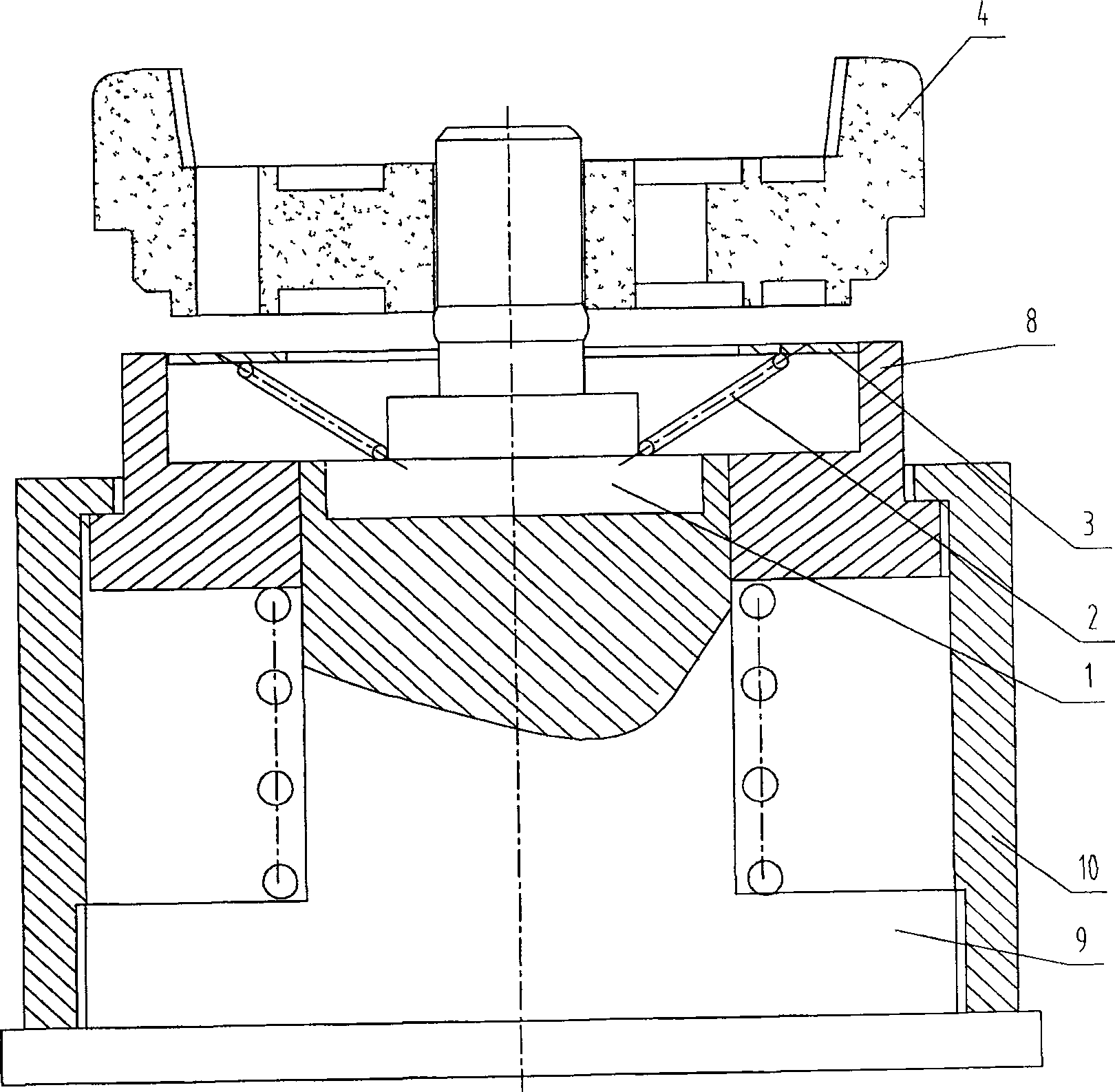
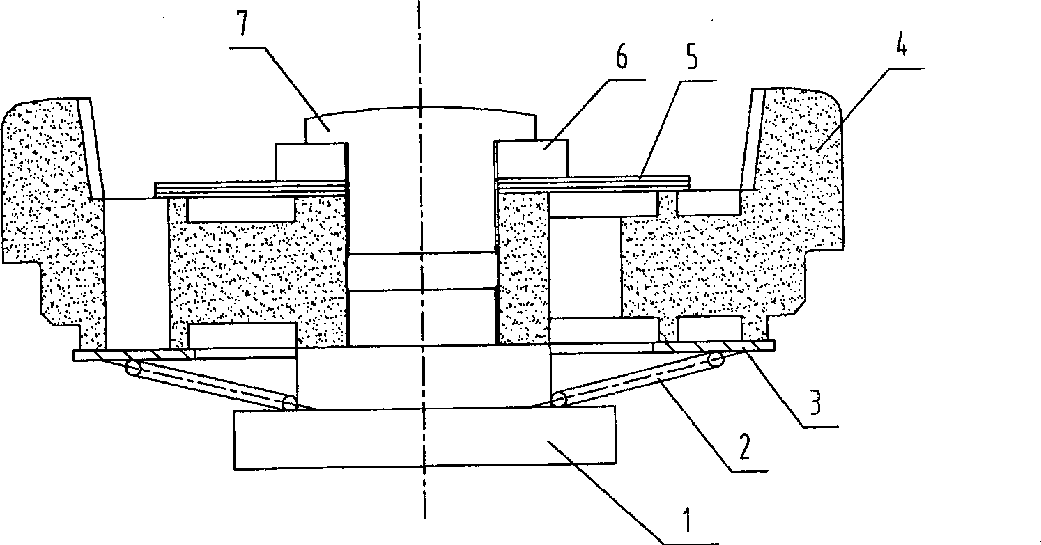
[0020] Depend on figure 2 As shown, the assembly process of the hydraulic shock absorber compression damping valve bottom valve subassembly includes the following steps:

[0021] 1) Process and assemble a special combined die, which includes a column 9, a guide cylinder 8, a limit sleeve 10 and a return spring. Groove, the guide cylinder 8 is provided with an inner hole that matches the compensation valve spring 2;

[0022] 2) Place the lower end of the bottom valve stem 1 with two steps in the groove of the column 9, with the small diameter end upward, and then set the compensation valve spring 2, the compensation valve plate 3, and the compensation valve spring on the bottom valve stem 1 in sequence. 2 stick to the first stepped end surface of the bottom valve stem 1 and locate in the inner hole of the guide cylinder 8;

[0023] 3) Put the bottom valve seat 4 on the b...


PUM


Abstract

The invention discloses an assembly technique for hydraulic pressure vibration reduction compressed damper valve base valve assembly. It includes the following steps: machining and installing a special combined die plate; putting the down part of base valve bar in vertical shaft flute of die plate, covering compensation valve spring, and compensation valve plate onto base valve bar; covering the bottom valve base on bottom valve bar; covering vibration reduction valve plate and baffle on bottom valve, taking rotating riveting to the upper part of bottom valve to make it compress the vibration reduction valve plate and baffle. The invention could produce high compressed damping force, high yield, and ensure consistency and lasting quality of the products.

Description

technical field [0001] The invention relates to an assembly process for a hydraulic shock absorber compression damping valve bottom valve subassembly. Background technique [0002] In the double-tube hydraulic shock absorber of an automobile, the function of the bottom valve subassembly of the compression damping valve is to generate the compression damping force and compensate the oil in the lower chamber of the working cylinder, to buffer the vibration of the vehicle body, and to complete the function of the shock absorber. The stability of the compression damping force plays a vital role in completing the vibration reduction function of the shock absorber. The assembly process of the existing bottom valve sub-assembly, such as figure 1 shown, including the following steps: [0003] 1) Place the bottom valve stem 11 with two steps and the upper end with a blind hole drilled on the workbench 18, with the small diameter end upward, and then set the spring 12, compensation ...

Claims


Application Information

Patent Timeline
Patent Type & Authority Patents(China)
IPC IPC(8): B23P21/00
Inventor 刘函唐旭东董万成
Owner 隆昌山川减振器工业有限公司
Learn More