
Optical fiber gyro front-set amplification and modification output circuit with signal differential amplification

A preamplifier circuit, fiber optic gyroscope technology, applied in Sagnac effect gyroscope and other directions, can solve the problems of many components, many digital filters, large common film noise, etc., to reduce power consumption and the number of components, Large output adjustment range, reducing the effect of noise introduction

Inactive Publication Date: 2009-06-10
BEIHANG UNIV
View PDF2 Cites 1 Cited by
  • Summary
  • Abstract
  • Description
  • Claims
  • Application Information

AI Technical Summary

Problems solved by technology

This kind of circuit uses many devices, the circuit is complex, the power consumption is large, and the amplification and transmission of analog signals pass through many devices, which is easy to introduce noise; and because most of them use single-ended amplification, the amplification factor needs to be It is doubled compared with the differential amplification, and the performance of the existing AD converter and DA converter is not fully utilized, and the common film noise is large
[0003] Using this kind of preamplification and modulation drive circuit makes the fiber optic gyroscope have a larger volume and power consumption, and uses more components; because the noise of the analog circuit part is relatively large, the common film noise at the input end of the AD converter has not been effectively suppressed. More digital filters are required in the signal processing process, which increases the difficulty of digital signal processing
Since the modulation step wave output uses a single-ended method, the amplification capability of the analog circuit is limited, which increases the burden on the drive amplifier circuit, and it is easy to cause the gyro output step wave to be offset.

Method used


Image

  • Optical fiber gyro front-set amplification and modification output circuit with signal differential amplification
  • Optical fiber gyro front-set amplification and modification output circuit with signal differential amplification
  • Optical fiber gyro front-set amplification and modification output circuit with signal differential amplification

Examples


Embodiment Construction

[0016] The present invention will be further described in detail with reference to the accompanying drawings and embodiments.

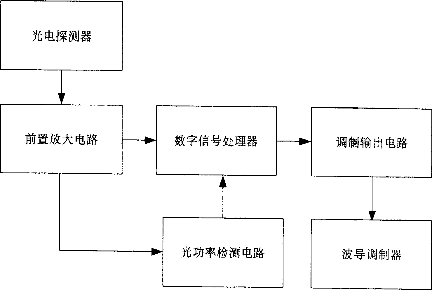
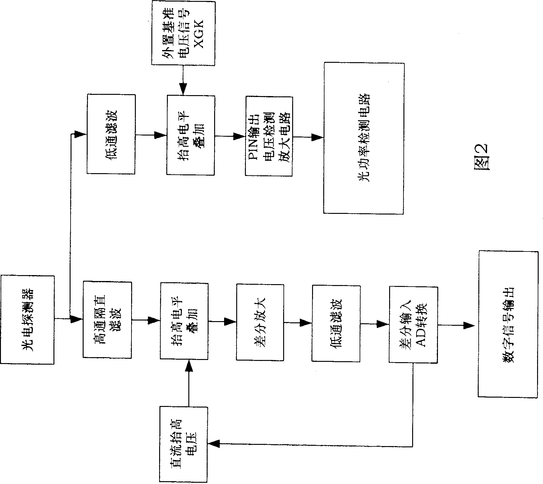
[0017] The invention is a fiber optic gyroscope pre-amplification and modulation output circuit with signal differential amplification, which belongs to the detection circuit part of the fiber optic gyroscope. The detection circuit generally includes a preamplifier circuit, a digital signal processor, an optical power detection circuit, and a modulation output circuit (see figure 1 As shown), the preamplifier circuit receives the light intensity voltage information output by the photodetector, amplifies it, filters it, and outputs it to the digital signal processor; the modulation output circuit receives the digital modulation information output by the digital signal processor, And it is amplified and then output to the waveguide modulator. The optical power detection circuit realizes the monitoring of the performance of the optical path.

[0018] P...


PUM


Abstract

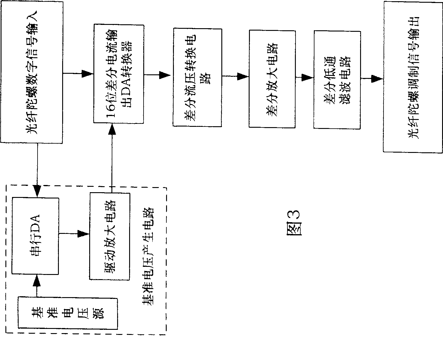
This invention discloses a fiber peg-top pre-amplification and modulation output circuit with signal differential amplification, in which, said pre-amplification circuit receives light strength voltage information output by a photoelectric detector and amplifies and filters it to be output to a digital signal processor composed of a differential amplifier, an operation amplifier and a 12-bit parallel AD converter, said modulation output circuit receives digital modulation information output by the digital signal processor to be amplified and output to a waveguide modulator composed of a 16-bit parallel DA converter, 10-bit serial DA converter, a primary voltage source, a differential amplifier and an operational amplifier. The voltage sphere of a ladder wave output by a modulation output circuit is 0V-+-4V and is designed in terms of specific double-differential current and voltage conversion circuit.

Description

technical field [0001] The present invention relates to a preamplification and driving circuit, more particularly, to a fiber optic gyroscope preamplifying and modulating driving circuit with signal differential transmission and amplification capabilities. Background technique [0002] Most of the existing preamplifier circuits for fiber optic gyroscopes adopt the form of single-ended amplification, using one or several stages of operational amplifiers to perform single-ended amplification on the output signal of the PIN and then transmit it to the AD converter, convert it into a digital signal, and pass the digital signal After processing, the modulated signal is converted into an analog staircase wave signal by a DA converter, which is converted into a differential signal by a multi-stage operational amplifier and output to the modulator. This kind of circuit uses many devices, the circuit is complex, the power consumption is large, and the amplification and transmission o...

Claims


Application Information

Patent Timeline
Patent Type & Authority Patents(China)
IPC IPC(8): G01C19/72
Inventor 金靖田海亭李敏
Owner BEIHANG UNIV
Learn More