Indoor air purifying device
An indoor air and purification device technology, applied in the field of air purification, can solve the problems of low packing density of flat membrane, poor air purification effect, poor separation effect, etc. Effect
- Summary
- Abstract
- Description
- Claims
- Application Information
AI Technical Summary
Problems solved by technology
Method used
Image
Examples
Embodiment 1
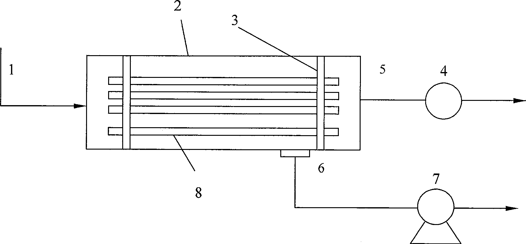
[0024] Indoor air purification device of the present invention such as figure 1 As shown, the device includes an air inlet 1 , a housing 2 , an epoxy resin head 3 , a fan 4 , an air outlet 5 , a VOCs outlet 6 , a vacuum pump 7 , and a hollow fiber 8 . The air inlet 1 is connected to one end of the housing 2, the housing 2 is connected to the vacuum pump 7, and the volatile organic compound outlet 6 is connected to the vacuum pump 7; the fan 4 is connected to the other end of the housing 2 and is connected to the air outlet 5 The epoxy resin head 3 seals the hollow fiber 8 into a shell side and a tube side, the hollow fiber 8 and the head 3 are sealed and airtight, and the space between the head 3 and the shell 2 is also sealed and airtight; Driven by the fan 4, the indoor air enters the shell 2 through the air inlet 1 and flows through the hollow fiber tube, the VOCs in it enter the shell side through the wall of the hollow fiber, and the clean air after removing the VOCs flow...
Embodiment 2
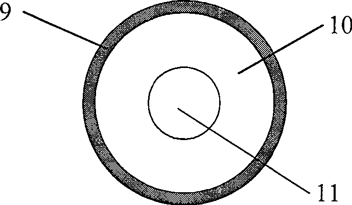
[0027] The specific structure of the hollow fiber of the present invention is as figure 2 As shown, the dense skin layer 9 is located outside the hollow fiber, and the porous support layer 10 is located inside the hollow fiber. Depend on figure 2 It can be seen that the indoor air goes through the pipe 11, and the porous support layer 10 of the hollow fiber is a porous support body with a thickness of 100-200 μm, including polyvinylidene fluoride (PVDF), polyetherimide (PEI), polypropylene Any one of nitrile (PAN), polypropylene (PP), polysulfone (PSU), etc., with a pore size of 0.4-2.0 μm; the thickness of the dense skin 9 is 0.2-5 μm, non-porous, and its material includes polydimethyl Any of siloxane (PDMS), polyether block amide (PEBA), etc.
Embodiment 3
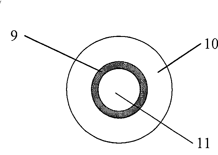
[0029] Another structure of the hollow fiber of the present invention is as image 3 As shown, the dense skin layer 9 is located inside the hollow fiber, and the porous support layer 10 is located outside the hollow fiber. Depend on image 3 It can be seen that the indoor air goes through the pipe 11, and the porous support layer 10 of the hollow fiber is a porous support body with a thickness of 100-200 μm, including polyvinylidene fluoride (PVDF), polyetherimide (PEI), polypropylene Any one of nitrile (PAN), polypropylene (PP), polysulfone (PSU), etc., with a pore size of 0.4-2.0 μm; the thickness of the dense skin 9 is 0.2-5 μm, non-porous, and its material includes polydimethyl Any of siloxane (PDMS), polyether block amide (PEBA), etc.
PUM
| Property | Measurement | Unit |
|---|---|---|
| pore size | aaaaa | aaaaa |
| thickness | aaaaa | aaaaa |
| thickness | aaaaa | aaaaa |
Abstract
Description
Claims
Application Information
 - R&D
- Intellectual Property
- Life Sciences
- Materials
- Tech Scout
- Unparalleled Data Quality
- Higher Quality Content
- 60% Fewer Hallucinations
Browse by: Latest US Patents, China's latest patents, Technical Efficacy Thesaurus, Application Domain, Technology Topic, Popular Technical Reports.
© 2025 PatSnap. All rights reserved.Legal|Privacy policy|Modern Slavery Act Transparency Statement|Sitemap|About US| Contact US: help@patsnap.com


